FacebookTwitterDiggGoogle BookmarksRedditLinkedinRSS Feed
Welcome, Guest
Username: Password: Remember me
This section of The Interchange provides a space where members of the Reading Modeler community can showcase their Reading modeling efforts. If you've got a project that you'd like to share, start a new topic and "show and tell" the group how you did it!
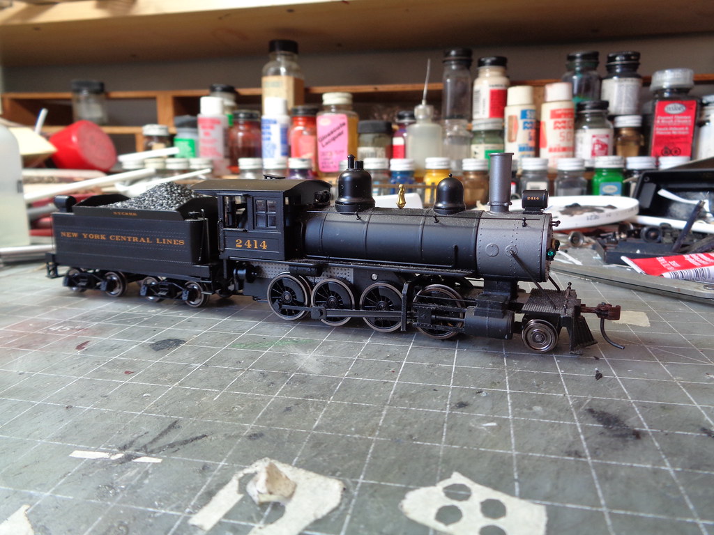
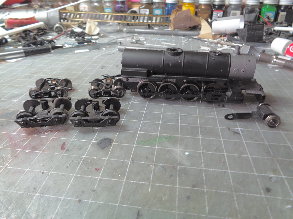
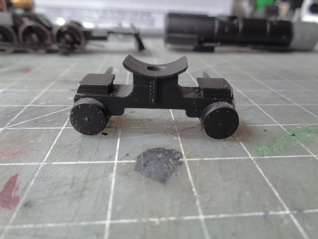
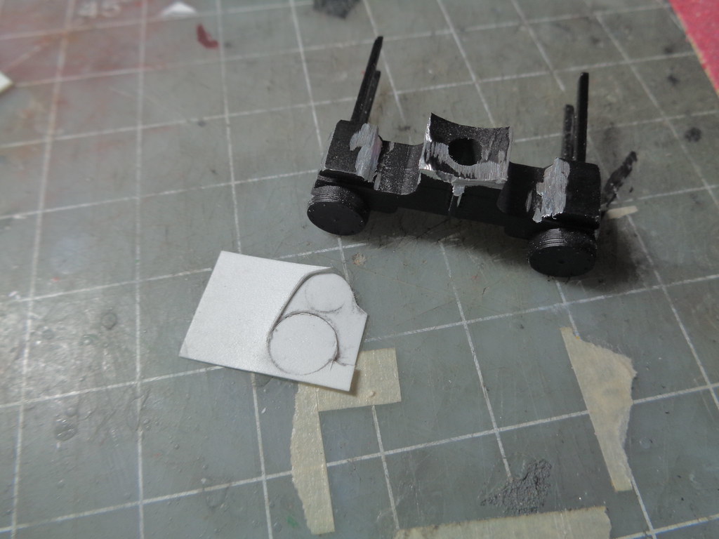
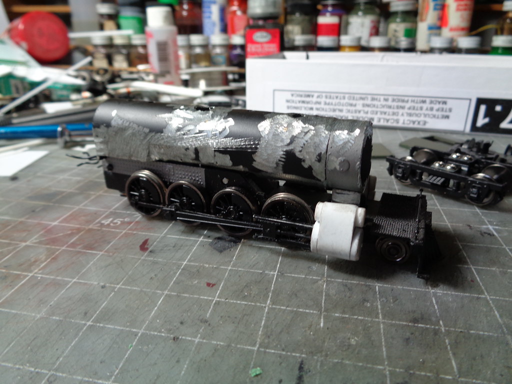
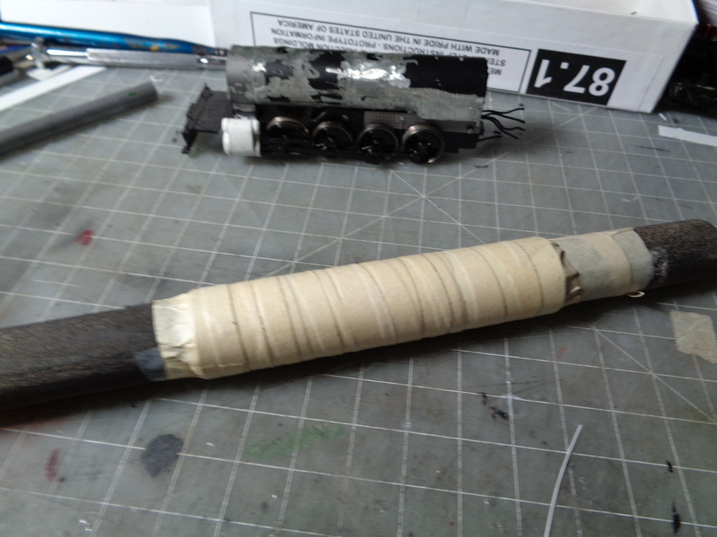
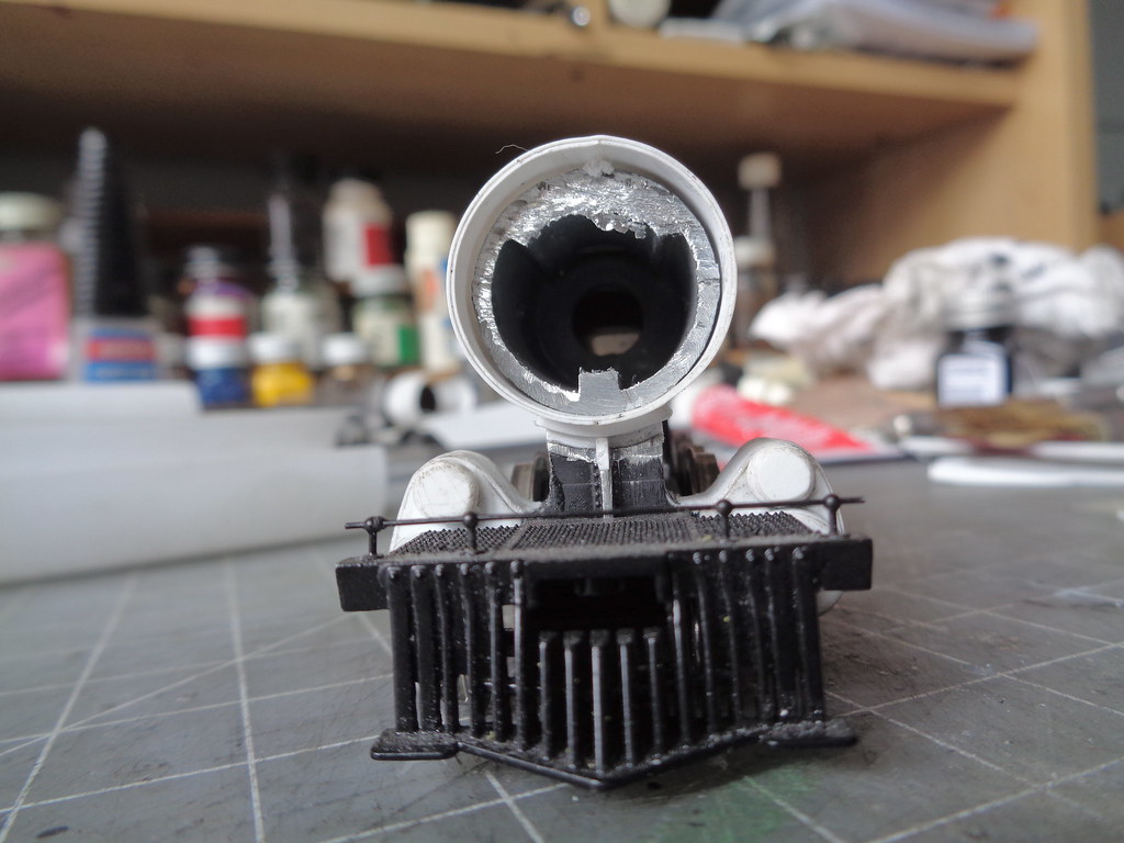
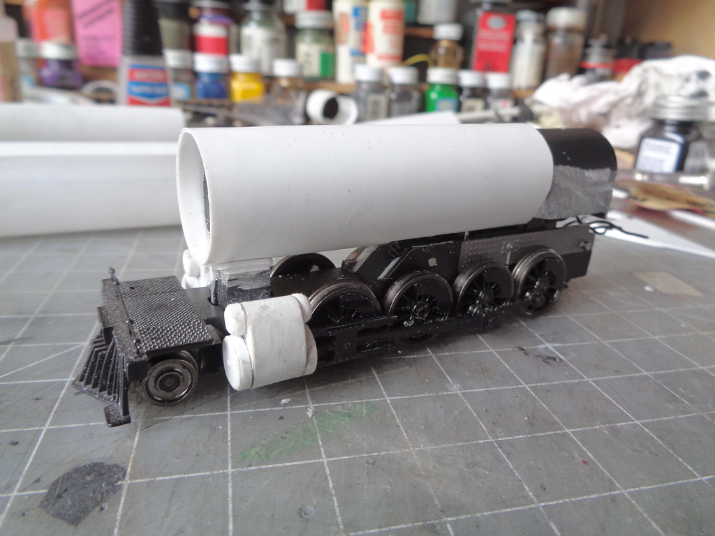
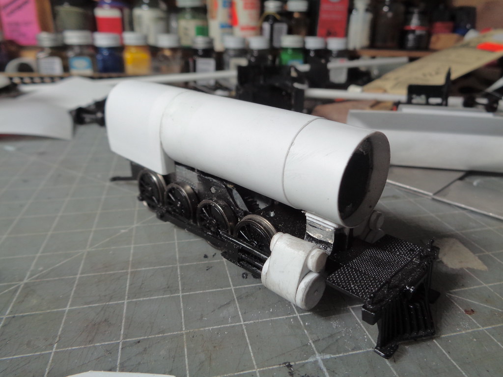
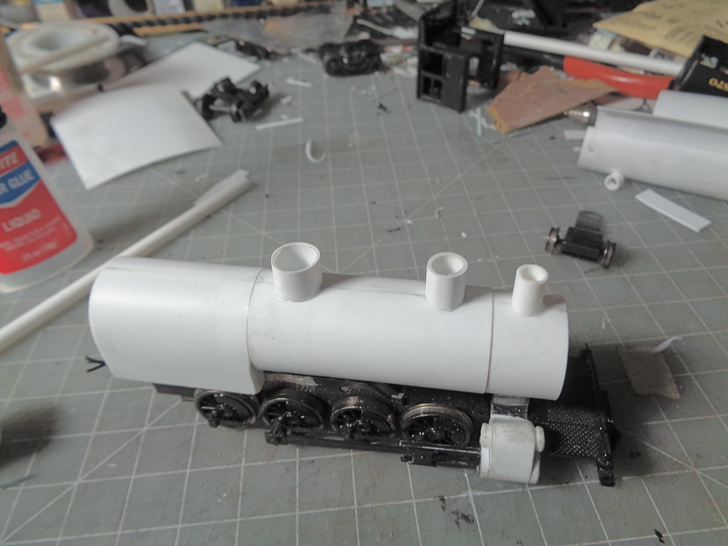
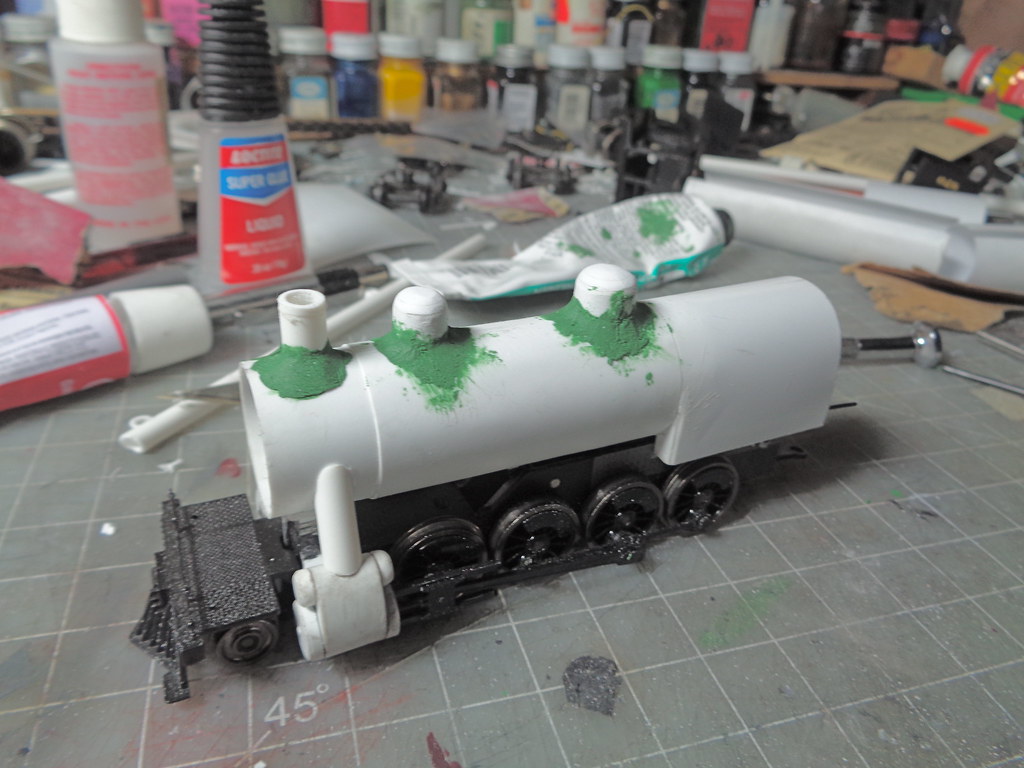
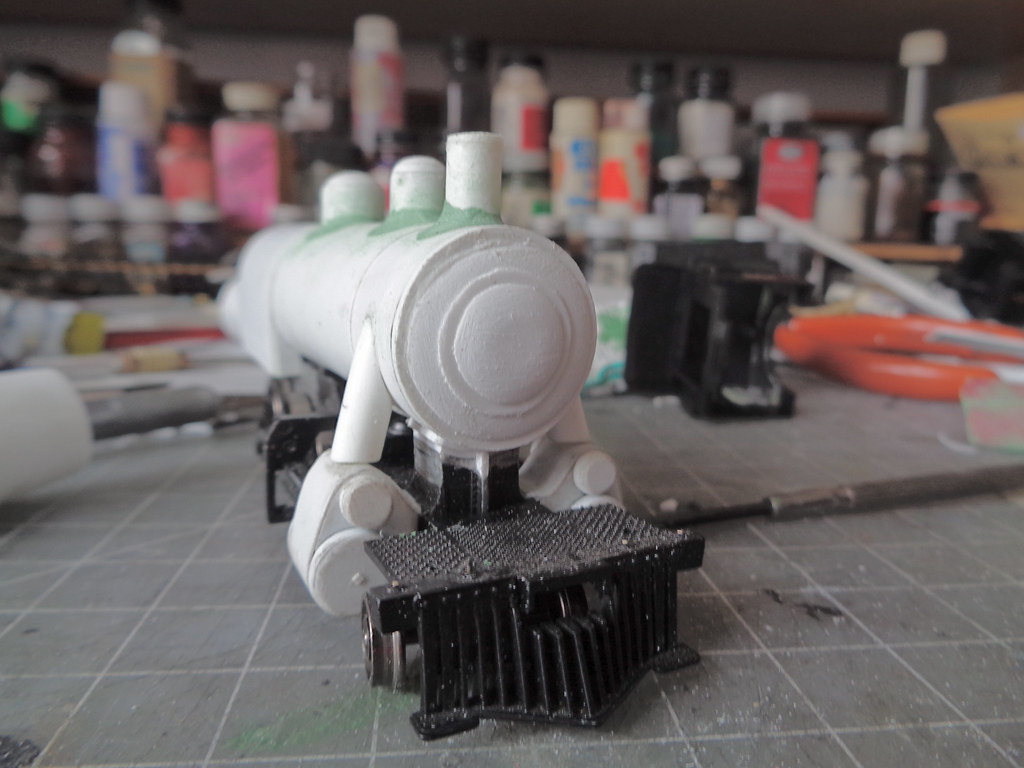
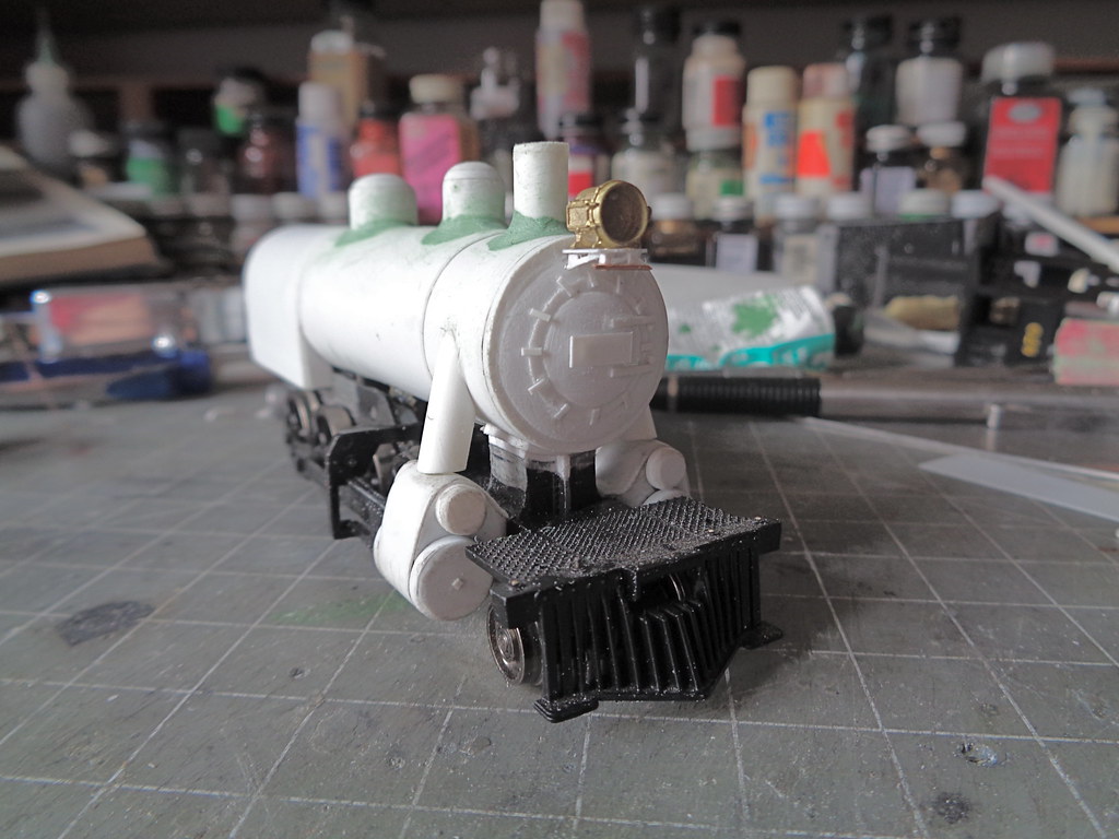
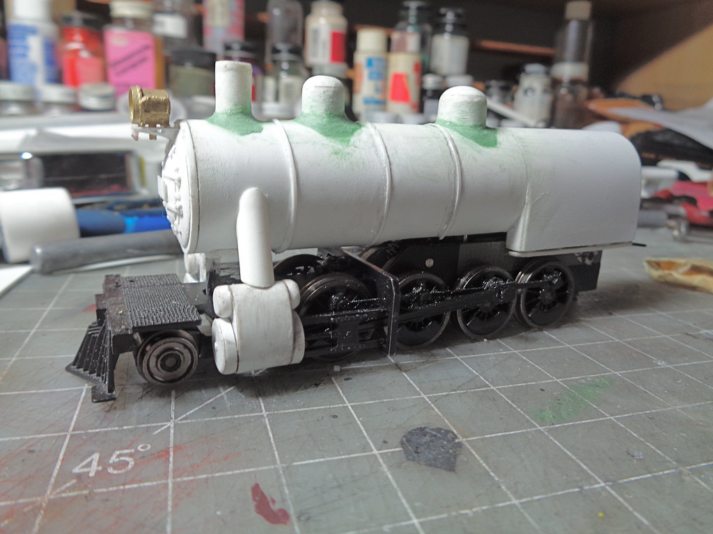
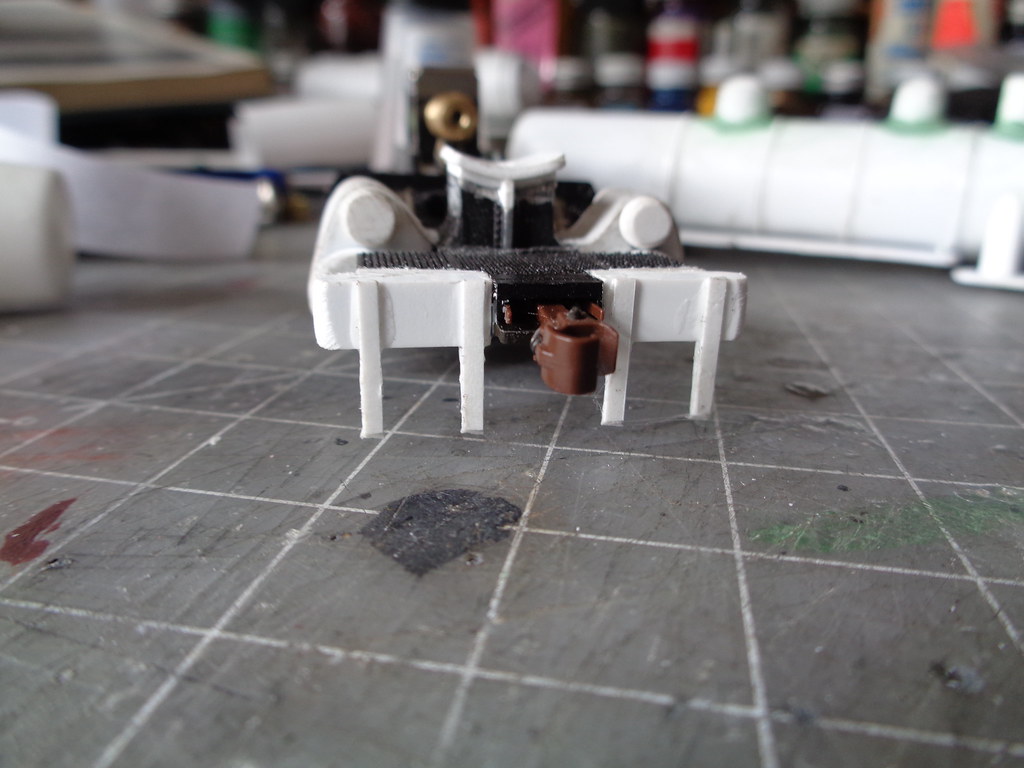
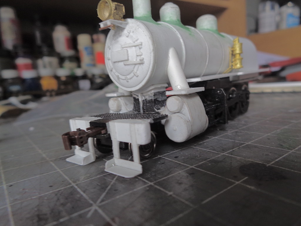
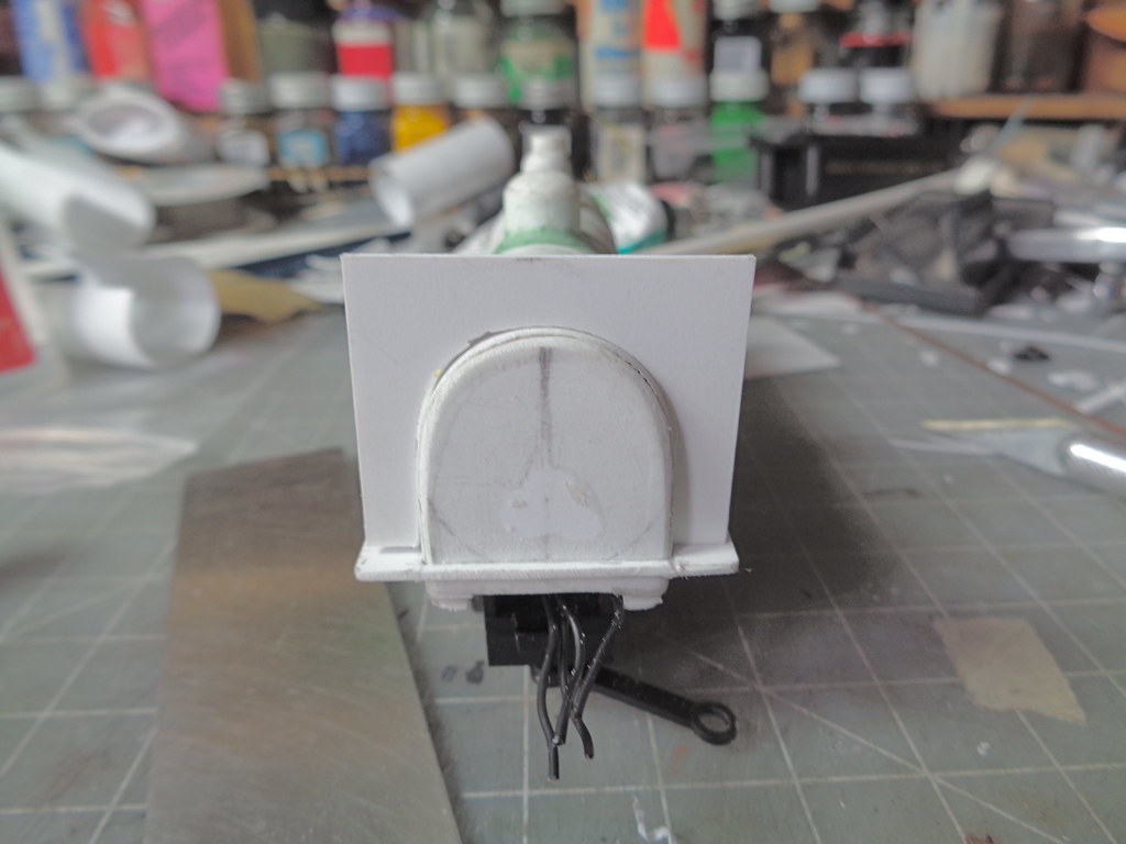
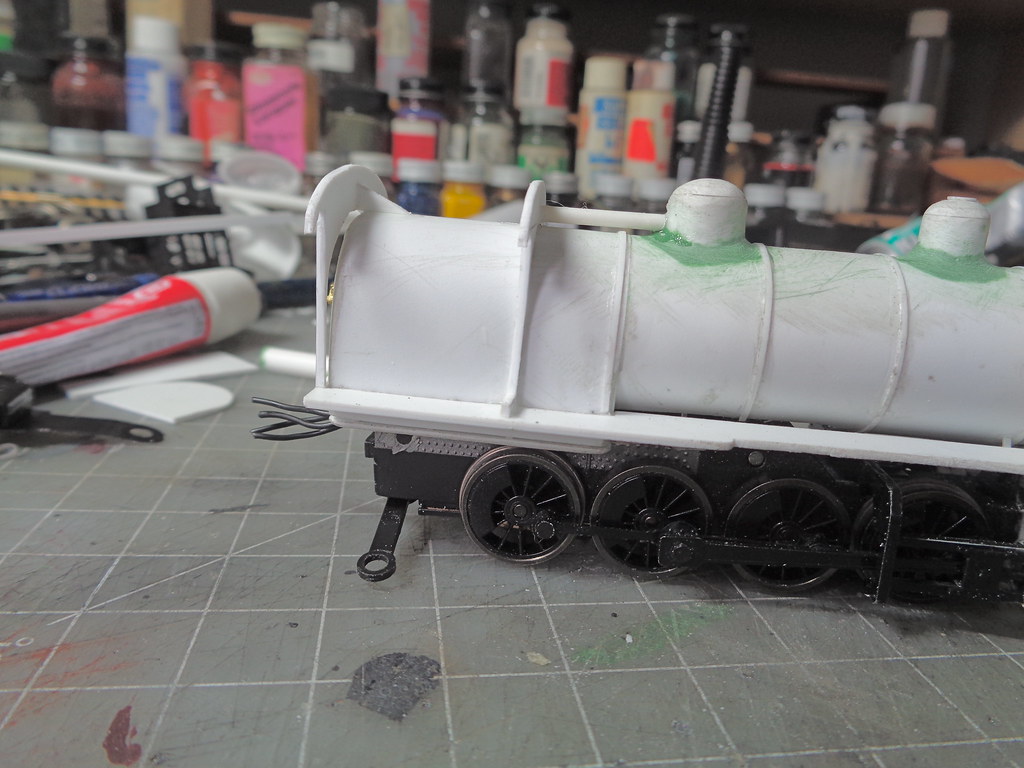
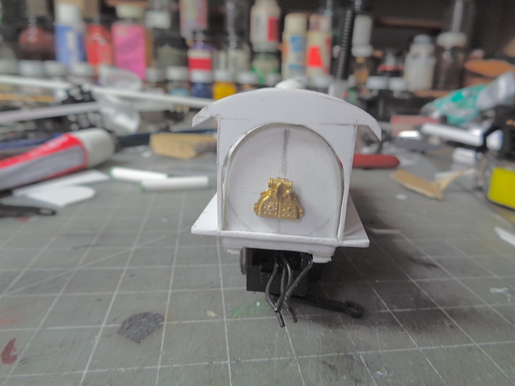
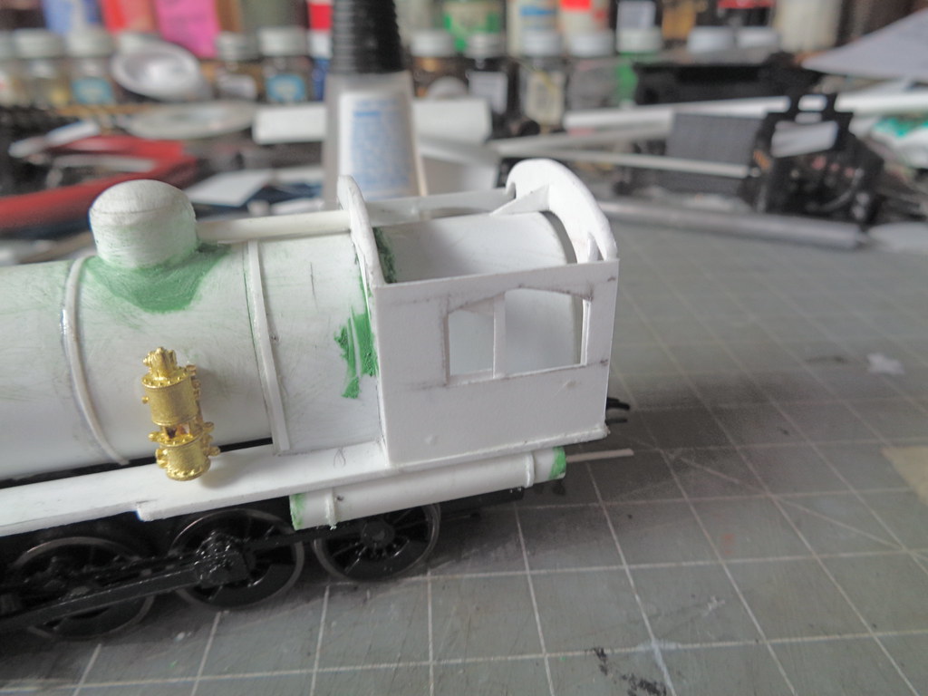
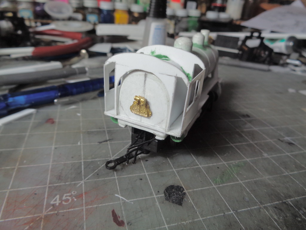
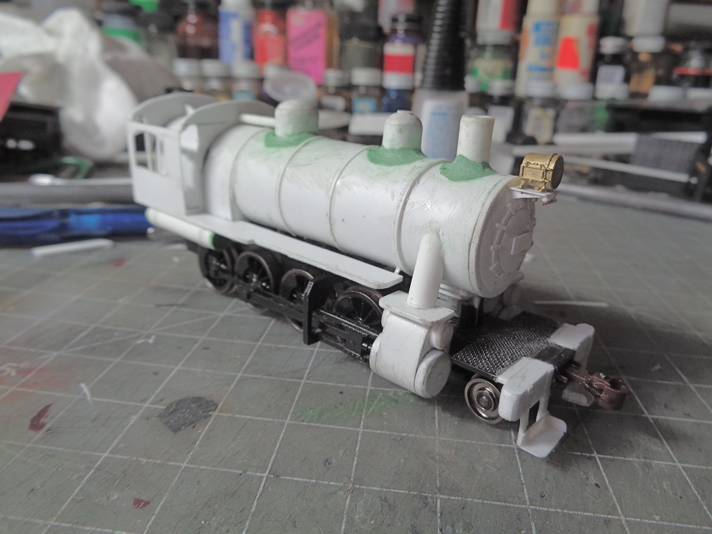
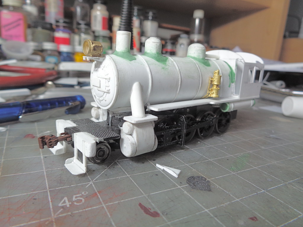
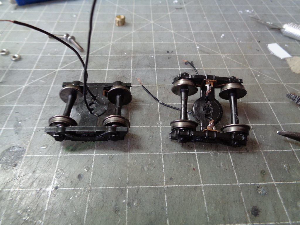
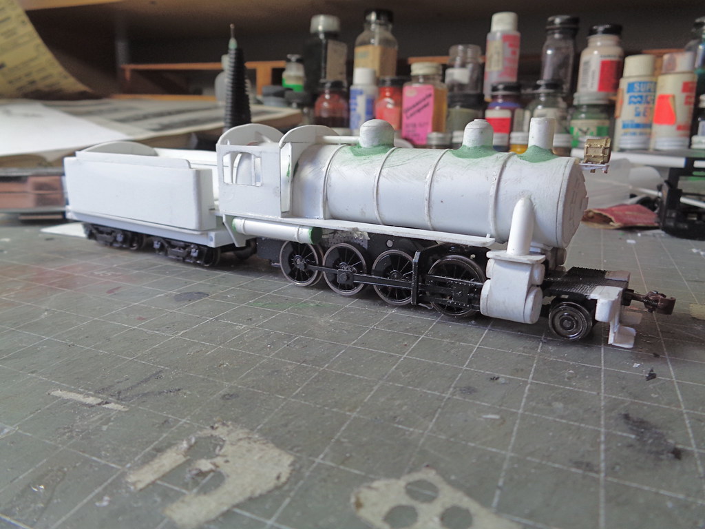
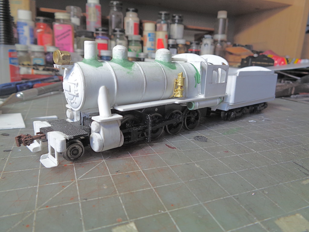
TOPIC: I-7 2-8-0

I-7 2-8-0 8 years 1 month ago #5162

  • Casey
  • Casey's Avatar
  • OFFLINE
  • Conductor
  • Posts: 209
  • Thank you received: 57
Next up is an I-7 built from a Athearn/Roundhouse old time 2-8-0 I picked up at the same show I got the 4-4-0 which is now the D-8. There are a couple ways to do this class of engine. There is the low set key hole firebox boiler version, the higher set wagon top slide valves, and the wagon top with piston valves. They are not highlighted very much but there were quite a few of these engines roaming the system.

To keep in my 30s-50s range I went with doing one of the later style versions of the class. Originally planning on keeping it slide valve, I changed my mind to do piston valve cylinders, mostly because I have not done a slide valve to piston valve conversion, so it was something new to try.

With all the variation in the large class this is basically what I'm going for.


This is the untouched Roundhouse engine.


The engine was quickly broken down to what is needed for the project.


Piston valve cylinders lean in a little on this class so the slide valve casting was ground down a bit on the outside then the inside of the box on top of the main cylinder. The saddle for the boiler was also ground down in preparation of an extension that will lift the boiler up.


In the picture above you can see the base template for the frame work in the conversion. This was done be placing the cylinders face down on a piece of .010 styrene and tracing the cylinder. The top piston was traced using the smallest tube stock I had with right side of the circles being on the same line, then I drew a connecting line for the outside of cylinder and drew another line to slope the frame into the original steam chest. The piece is then cut using the lines as a guide. once one is made you can trace it to make the three others needed.


The pieces are then glued saddling the original piston, I eyeballed the angle they sit based on pictures.


A piece of .010 is then glued to the frame starting close the the under side of the steam chest, wrapping all the way around to the steam chest again. The oricinal cylinder head was wrapped in .010 as well to bring it up to the same level as the new side wall and then I capped it with .010 and sanded the edges a little round to not have a hard edge. The stop piston was cut from tube stock to be the same width as the lower driving piston.


The top piston is then also capped with .010 and also sanded to not have a hard edge.


Once one side is done just repeat for the other.


Now that the cylinders were set up attention shifted to the boiler. The plan is to use much of the weight of the original boiler, but resetting it in a way with a new tube making the boiler slightly bigger. To do this most of the detail was ground off. The smoke box was also cut shorter since Reading smoke boxes in general are quite short, I did keep the original mounting hole for the screw.


This is the new boiler tube taped up being 5 layers of .010, the top 3 will be used.


While setting the cured tube to what was left of the shell the steam chest extension was set in two layers of .040. One layer trimmed to the size of the chest and the top layer is set a little bigger for the boiler saddle.


This is where it sits at the moment.
The administrator has disabled public write access.
The following user(s) said Thank You: tcalvin48

I-7 2-8-0 8 years 1 month ago #5177

  • Casey
  • Casey's Avatar
  • OFFLINE
  • Conductor
  • Posts: 209
  • Thank you received: 57
The putting a fire box on the tube is not really different then putting a wooten firebox on, the frame goes trait down from the boiler instead of getting wider.


This one I tried something a little different and set the bottom for the firebox, or mud ring, before wrapping the sheet of styrene over the frame. It was easier to set next to the reused metal weight without the sheet there. Once the wrapped sheet was in place and trimmed the jacketing layer was added on the rest of the boiler to match the height of the firebox sheet. The hard edges of the firebox were then sanded.


The stack and domes start with the main barrel shape. The stack is a piece of tube stock the domes were pieces of .010 coiled up and glued to itself, with the seam being sanded smooth.


While the dome bases were drying I made the steam delivery pipes from tube stock.


The domes were trimmed down and capped with 2 layers of .040 styrene. Those layers were shaped by sanding, the steam dome on the I-7s were not a full dome shape on the top, it was a flatter dome with a harder angle on the outer ring. Once the tops were shaped putty was added at the bases and allowed to dry over night.


The bases were then sanded to slope into the boiler.


I decided to make the smokebox front removable to make getting the headlight wires in easier. Since the boiler is made up of the outer three layers of five used to get the width needed, I cut a strip from layer two, glued the ends together and glued the ring down on a piece of .040. This makes for an easy snug friction fit. The .040 was loosly cut out over sized and sanded flush to the boiler in place.


The rest of the smokebox front is done in the layers of .040, .010, .040 on top of the already made base. The bottom layer sanded to be the puff out, the .010 to be the base flat part of the door, and th e top .040 being the puff out of the door. Then the layers were glued on the base.


The latches, hinges, number board and headlight bracket quickyl followed, all made of .010 styrene. The engine now has a face.

The administrator has disabled public write access.
The following user(s) said Thank You: tcalvin48

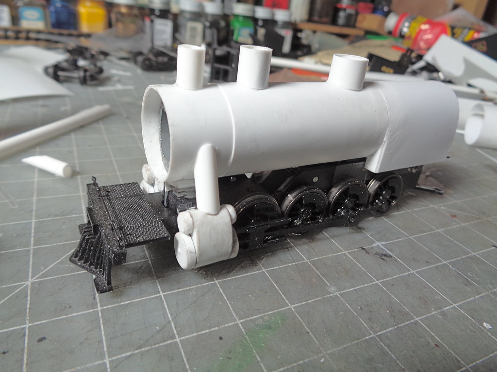
I-7 2-8-0 8 years 4 weeks ago #5189

  • Casey
  • Casey's Avatar
  • OFFLINE
  • Conductor
  • Posts: 209
  • Thank you received: 57
The boiler bands were next to go on except the one towards the front of the firebox, I wanted to get the running boards placed first. These are strips cut from .010 styrene. Also an ash pans was place, that will mostly be blocked by air tanks later, space with .010 pieces making sure they did not rub on the drivers.


The running boards were made from .040 starting with the section glued to the steam delivery pipes on the cylinders, then the main running board. The main running boards step in at the third driver with rounded corners. They are glued to the side of the firebox, and I used a small .010 scrap piece as a brace to the boiler on the front of the running board.


While the running boards were setting I started work on the pilot, using a dremel to cut the old one off to the coupler pocket.


The new pilot beam was glued to the couple pocket sides and the extra space filled with scrap styrene.


Making a foot board pilot is really just the vertical frame with the boards attached. I build it right on the pilot starting witht he vertical frame.


The cab on these engines sit on top of the fire box ending at the back head, so though these engines were not anthracite burning or camelbacks they would have felt like you were basically running the same thing in the cramped cab. The cab starts with the front and rear walls making the width just under edge to edge of the running boards the height of the steam dome. setting the piece on the running boards on the rear I traced the boiler shape to be cut out of the sized cab wall piece.


Where the roof slopes down to was eyeballed to be at the height of the boiler and was cut out with the doorways. I left a little foot on the front wall the rear wall was cut strait down as you would not be wanting to trip over that all day working on the engine. The rear wall was set at the end of the running board with a little anchor piece at the top, which in the end will be hidden. The cab length was set based on average cab sizes. The rod coming from the steam dome would be a cover/guide for extended throttle linkage, another set up borrowed from camelbacks on these engines.


The cab sides are .010 with window frames put in before the sides are set, just easier in order that way. The air tanks were also set at this time.


Still without a tender, starting to look like an I-7.


The administrator has disabled public write access.
The following user(s) said Thank You: tcalvin48

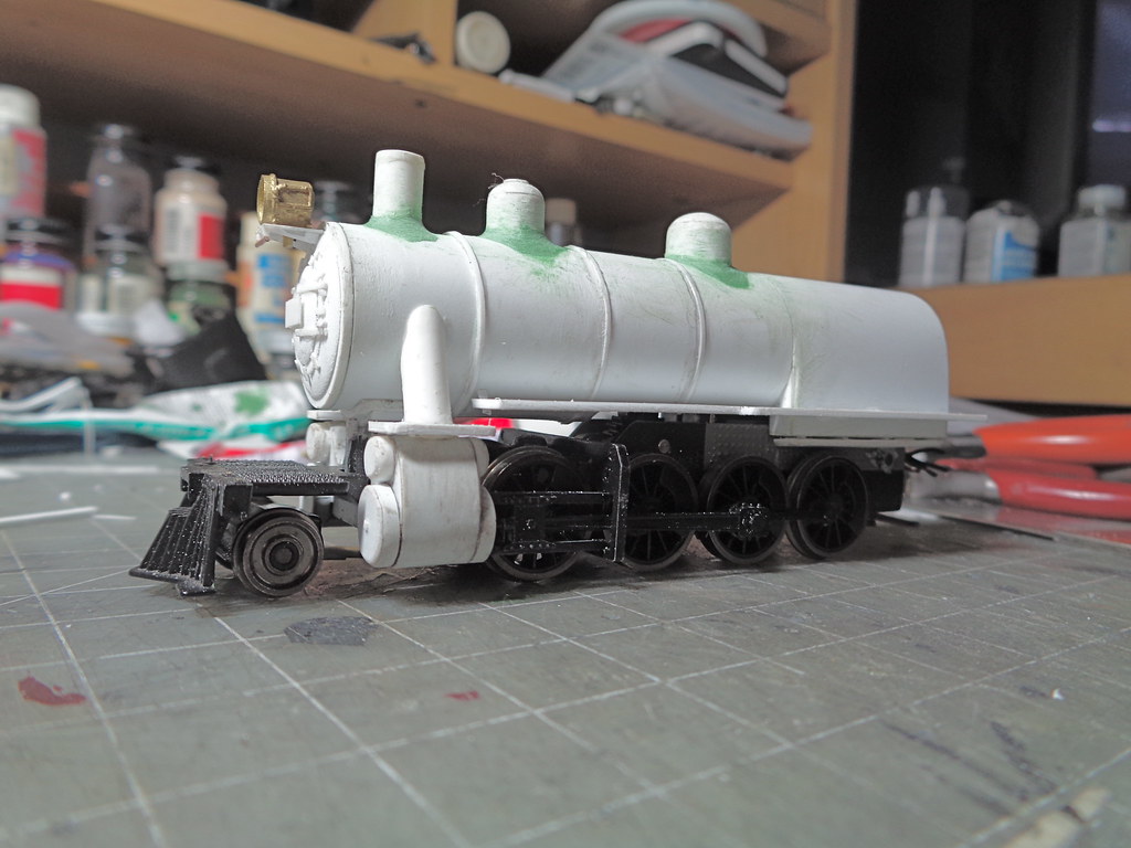
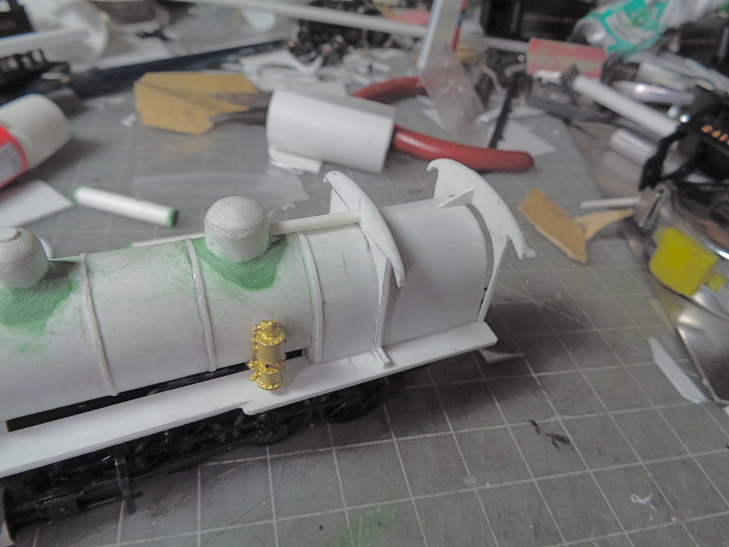
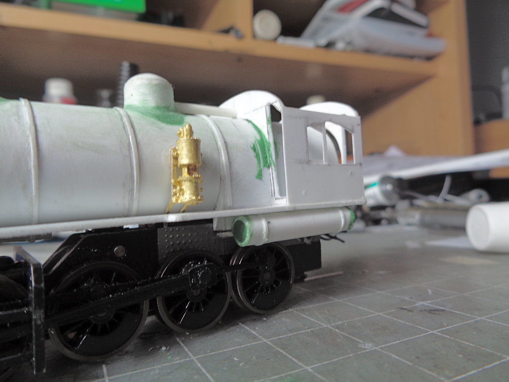
I-7 2-8-0 8 years 3 weeks ago #5201

Casey, do you think this build would work with the older MDC/Roundhouse kits?

Mark
The administrator has disabled public write access.

I-7 2-8-0 8 years 3 weeks ago #5203

  • Casey
  • Casey's Avatar
  • OFFLINE
  • Conductor
  • Posts: 209
  • Thank you received: 57
I don't see why not. The only real reason I am using a newer Athearn release is the newer motor.
The administrator has disabled public write access.

I-7 2-8-0 8 years 3 weeks ago #5205

  • Casey
  • Casey's Avatar
  • OFFLINE
  • Conductor
  • Posts: 209
  • Thank you received: 57
Shifting focus to the tender, I started with salvaging the original pickups and fitting them to Bachmann trucks. The bearing pocket needs to be drilled out a little to fit the metal one, and the pickups fit best up side down from the way they were positioned on the original arch bar trucks. The old clip mount of the bachmann trucks gets cut off and a hole is drilled for a mounting screw in the center. The wires run through holes conveniently in the original molding of the truck.


The tender frame is made of .040 styrene starting with main flat plate, then the end beams are added. The side bars running the length and the center spine are then fit to inside the space of the end beams. The spine is made up of 3 layers with 2 additional layers as pads for the trucks. Holes are drilled on both sides of the main spine for the wires.


The shells starts with the main tank , gluing the back and sides together. On this one before the front opening pieces went in a gave the box some stability by adding the rear top plate in first. Then the front pieces went on followed by the top front pieces. Two .040 strips were added to the inside corners as filler for sanding the corners round. This allows a broader curve with out jeopardizing the structure.


The rest of the coal bunker was then filled out which does not have to be shaped like this since with will realistically be covered in coal when done. The gangway height is set by having the shell on the frame and marking the height a little lower then the cab floor of the engine so make room for a foot plate.


Then the corners were sanded.


The top of the coal bunker was next. It was not very tall on these tenders though some had an extension, I'm thinking this one will not have one. The rear of the tender was pretty much just big enough to fit the water hatch with the light sitting kind of oddly, but I will get to that later.


Here is an over view with the tender.


The administrator has disabled public write access.
The following user(s) said Thank You: tcalvin48
Time to create page: 0.113 seconds

Today's Image

Did You Know?

June 20-23, 1972
The Reading is devastated by Hurricane Agnes; washouts and damage across the system require significant effort to repair, and also hasten the abandonment of marginal branches.

Downloads

Operations Information

Click Here!A variety of Reading Company operations related documents, etc. that may be of use in your modeling efforts.

Operations Paperwork

Click Here!A variety of Reading Company operations paperwork, such as train orders, clearance forms, etc. that will help you operate your Reading layout in a prototypical manner.

Timetables, Rulebooks, Etc.

Click Here!Public Timetables, Employe Timetables, and Rulebooks that provide much useful operational information.

Modeling Goodies

Click Here!Signs, billboards, and other FREE goodies for your use.  We ask only that you help spread the word about The Reading Modeler!

Rolling Stock Reference

Click Here!Downloadable reference documents on the various classes of Reading Company Freight and Passenger rolling stock.

Thanks for Your Support!

If you find the content on The Reading Modeler valuable, won't you please consider supporting our efforts? Your donation will help to offset operating costs and acquire new material to share on the site. Thank you!

Amount: 

Advertisements