To start the actual locomotive I started with the pilot. In the past I used a pilot from Greeyway products which I picked up at train shows in Timonium MD directly from the company. I do not have a specific part number and they don't even have what I got on their site but they have something close thats.... out of stock right now, so good thing I figured out scratch building one. At any rate here is the link to Greenway products part TS-696
www.greenwayproducts.com/storeroom/brass...ilots_snowPlows.html the one I got from the company was only the pilot no boiler struts, hoses, cut lever, etc.
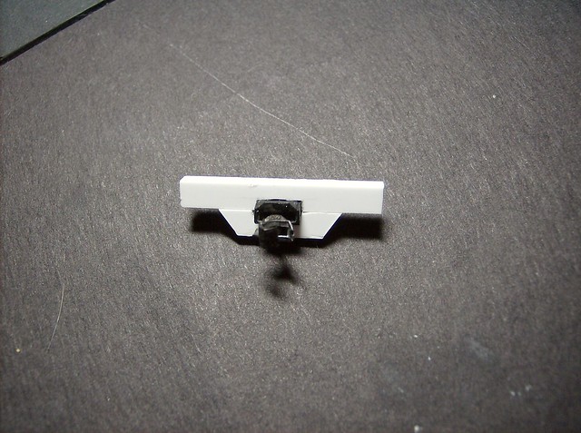
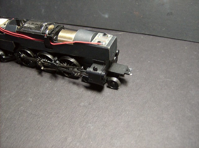
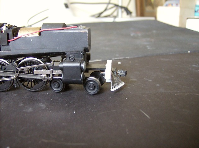
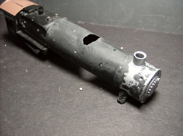
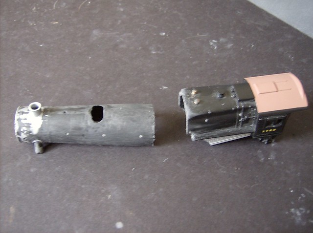
Start by taking off the K-4 pilot which slides off with a little muscle once the coupler is removed then remove the tab on the frame so it is flush with the base frame.
The pilot starts as .125 x .188 strip of styrene cut to 1 5/16 length. the coupler pocket is a normal kadee no.5 with the round holes that stick out the side cut off to be a solid rectangle. make a notch the width of the coupler pocket centered on the beam 3/32" deep for the coupler pocket to fit in. The lower section is the same stock fit to have 1/4" of the top beam stick out and have angled cuts on the ends to be a little less visible in the finished product. Also notched in the center 3/32 to fit the other half of the coupler pocket and then all glued together with the pocket sticking out about 1/8".
The rest of the pilot gets a little tricky to explain, it was a lot of eyeballing and deciding what to do as I was doing it, but I started with making a line on the pilot in line with the top of the coupler pocket which is the drill line for the top bars and a second line under the coupler pocket as the drill line for the lower bars that go under the coupler. Starting 3/16" from the sides I made 6 center punches on the line 1/16" apart by using a sewing needle and just pressing it into the plastic. then center 7 more holes on the lower line using the same center punch.
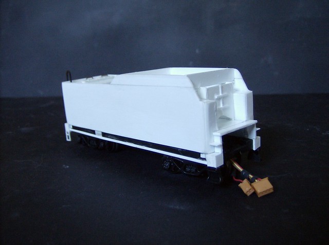
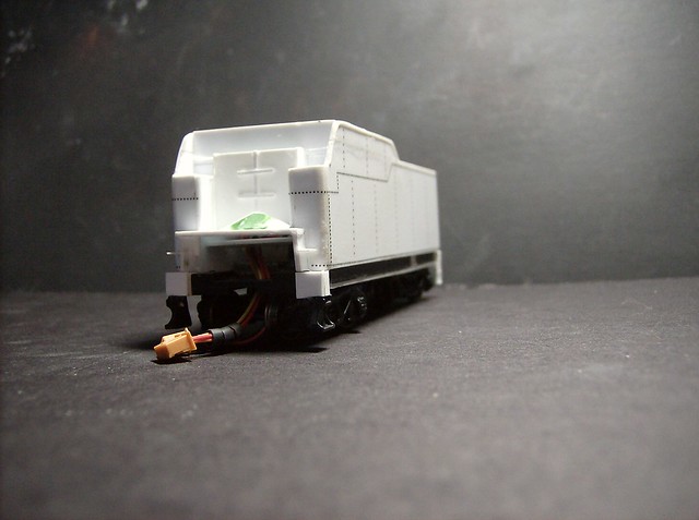
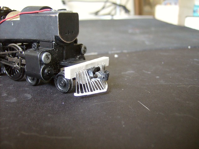
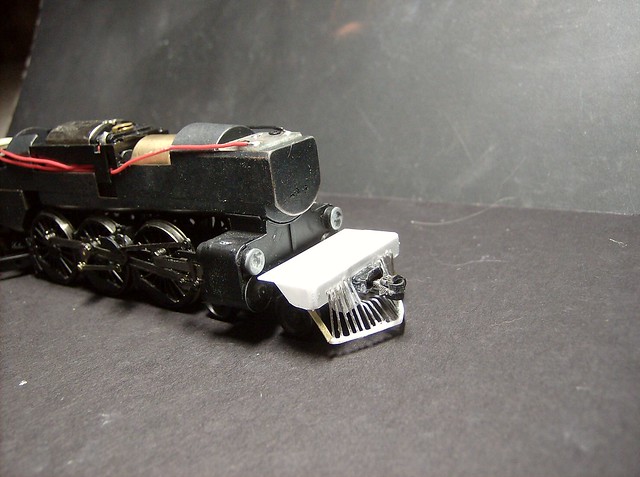
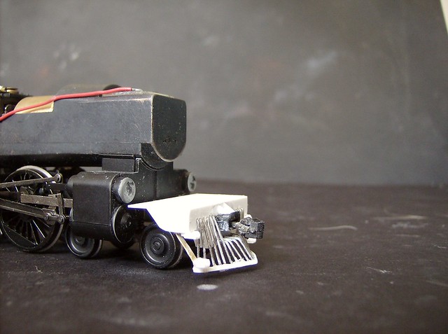
At this point glue the pilot onto the frame centered and so the top is not quite flush with the top of the frame, it needs to be flush the a piece of .010 inserted later. Then I started adding the pilot "pipes". This was done at the end of a table so I could bend and position each rod then cut to a good consistent height that will clear the track and switches. As I said a little hard to explain and I don't have specific measurements as I mostly eyeballed it, but all the rods are bent into little L shapes and tweaked from there the bottom pieces being a little more equidistant.
After all the rods are in place I added a strip of .015 x .030 and glued all the rods to it making it much more solid as a piece. You will also see that the piston valve (top cylinder) has been sanded to be rounder, done so further hide it's pennsy origins. The orange slice snifter valves get broken off too I just hadn't done it at this point.
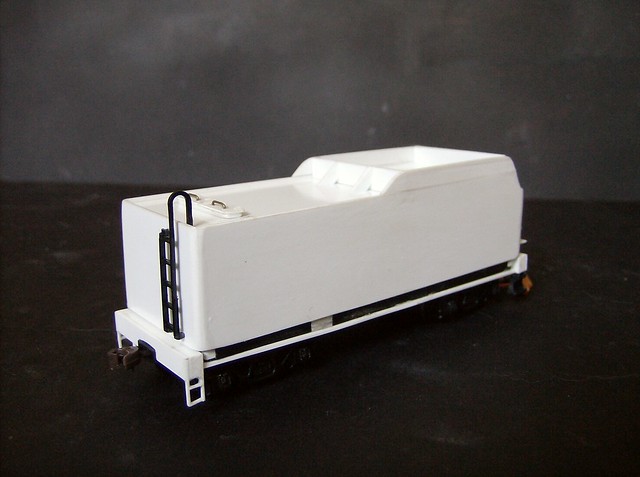
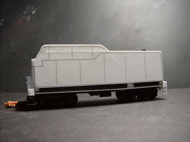
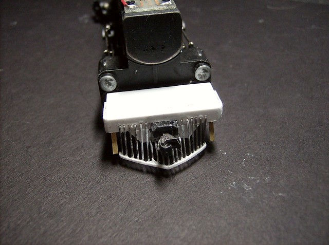
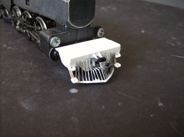
Next the piece of .010 is added to be flush with the top of the pilot beam measuring 1/2" x 1 5/16". Then the for decorative pilot swoosh piece can be glued on the side made from .010 measuring the height of the pilot beam 3/8" on top and 1/4" on the bottom then cut to connect the dots and sand a curve in the bottom corner. Once glued into place sand the front corners of the pilot to give it a round edge. You will see the pilot steps started with a piece of brass .010 about a width of 1/16" about 1/2" long glued to the back of the pilot and bent to stick out a little past the first rod sticking down on the pilot.
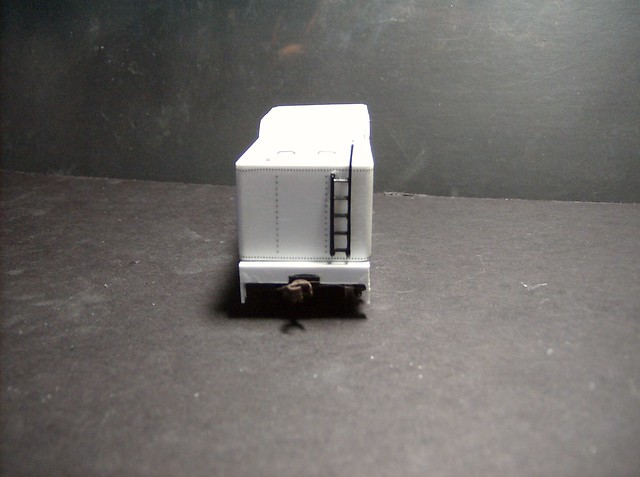
The steps themselves are made from the .015 x .030 strips then bridged by a mall piece of .010. The two vertical pieces are set about 1/8" apart the top step glued to the underside of the pilot beam the bottom step glued to the brass. You will also see the coupler pocket bracing which are just little triangles made from .010.


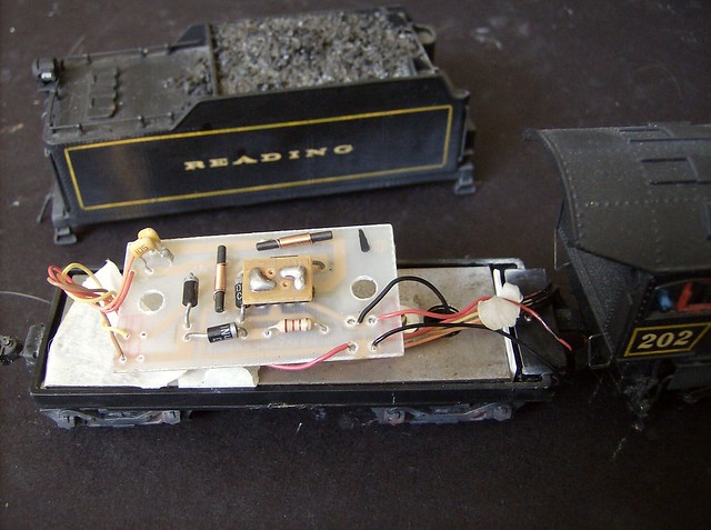


 A variety of Reading Company operations related documents, etc. that may be of use in your modeling efforts.