FacebookTwitterDiggGoogle BookmarksRedditLinkedinRSS Feed
Welcome, Guest
Username: Password: Remember me
This section of The Interchange provides a space where members of the Reading Modeler community can showcase their Reading modeling efforts. If you've got a project that you'd like to share, start a new topic and "show and tell" the group how you did it!

TOPIC: Semi-streamlined G-2sa

Semi-streamlined G-2sa 10 years 9 months ago #1586

  • Casey
  • Casey's Avatar
  • OFFLINE
  • Conductor
  • Posts: 209
  • Thank you received: 57
This project came about because I had originally gotten the base Bachmann PRR K-4 to do a G-3 thinking that I could get a boxpok driver in the frame, that didn't work so it sat for almost a year. One weekend I decided to see if I could reverse what I did which did work. I was debating what to do with it kind of settling on either, CNJ, LV or Reading but it ran so well with my already built 202 I decided Reading was the way to go. Its not going to be a copy of what I did especially since 202 is pretty specific in details being the only semi streamlined pacific with an exposed smokebox and injector pipe and it also had the original tender which is basically an I-10 tender. I intend on covering the differences in build between the 2 as well.

This build will be one with the upgraded tender and a more standard look of the semi streamlined pacifics, looking very much like this picture of 176 when done.


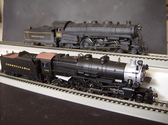
202 was built using many parts from an I-10 such as domes, firebox and cab and tender shell and trucks, This one will be cheaper to make but takes more skill as I intend to scratch build just about everything I can. So to get started here is the starting picture of the K-4 and my 202.


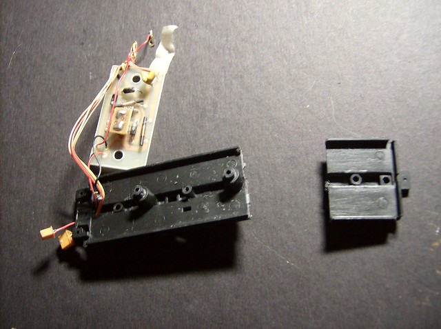
Lets start with the tender. If you really look at the Reading upgraded G-2s they got a lot of PRR characteristics like the fact that the tender trucks are basically the same as the existing PRR trucks on the K-4 which saves time and money since you don't have to find them. These tenders were large held more water then G-3 tenders by 1500 gal. they were a little shorter but taller then the G-3 tenders, so the tender frame needs to be cut and extended. Remove the old shell but don't totally disregard it a few things are salvages off it and remove everything from the frame you can, the only thing that stays is the circuit board because the wire plugs are too big to fit through the hole in the frame so just push it to the side.


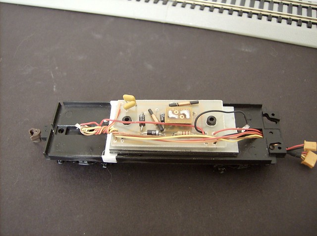
I made the cut just behind the rear nob the circuit board sits on so it sits the same and you can keep the under frame detail as is.


The spacer is .040 styrene that is .25 of an inch glued flush with the original frame then 2 other pieces to fill the gap created on the vertical wall. then you can put everything back on the original wire should stretch back to the new position and still have the board sit where it was, I put a little dab of glue on the nuts when in place to keep them from working loose.
Last Edit: 10 years 8 months ago by Casey.
The administrator has disabled public write access.

Semi-streamlined G-2sa 10 years 9 months ago #1587

  • rdg5310
  • rdg5310's Avatar
  • OFFLINE
  • Conductor
  • Posts: 265
  • Thank you received: 39
Looking forward to this build! :)
The administrator has disabled public write access.

Semi-streamlined G-2sa 10 years 9 months ago #1588

  • Casey
  • Casey's Avatar
  • OFFLINE
  • Conductor
  • Posts: 209
  • Thank you received: 57
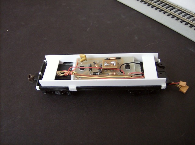
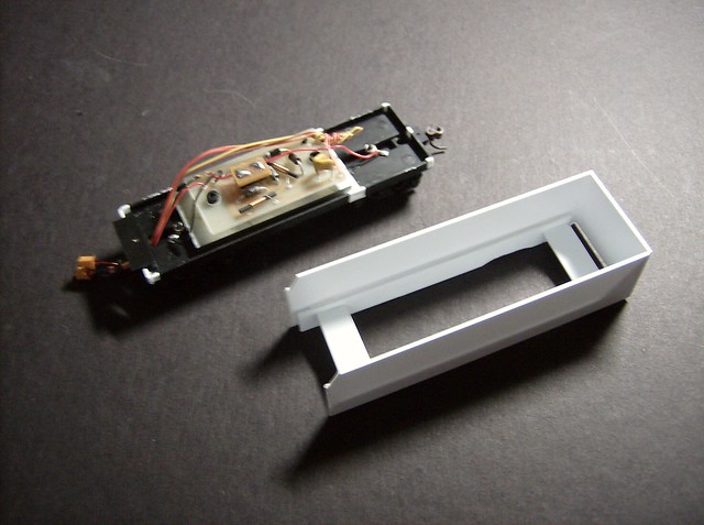
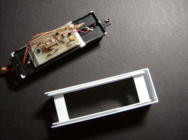
Next I filled in the remaining gaps in the frame with more .040 styrene making a solid ring to the draw bar from on the front of the tender, then started the base frame for the tender shell to be attached to which is more .040 cut into strips that rest against the inside walls of the original frame then glued together with spacers eyeballing them to be vertical against the frame walls. this creates a removable piece so you can access the internal electronics and is NOT glued to the frame itself. It does not need to look pretty it purpose is to have something to build off of. I also cut out notches to go over the spacer to lengthen the frame, the glue was a little built up and it didn't want to sit flush over it.
The administrator has disabled public write access.

Semi-streamlined G-2sa 10 years 9 months ago #1599

  • Casey
  • Casey's Avatar
  • OFFLINE
  • Conductor
  • Posts: 209
  • Thank you received: 57
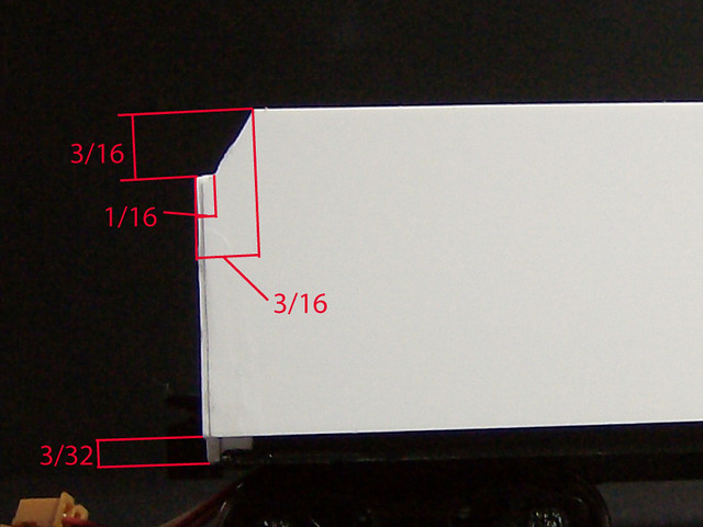
Now that there is a sturdy base frame I added another layer of .040 to the side which rather conveniently made the built frame flush with the original frame walls. Next is to cut out one of the sides, I stuck with the .040 to give the depth off the original frame. The side will lit lower then the top of the original frame edge but not cover all of it. I measured up 3/32 from the bottom and made a mark on both ends of the original frame, I made the marks on the white filler pieces added earlier for visibility, this will be where you line up the bottom of the side pieces.

For the side piece start by cutting a 4 8/32" x 1" rectangle (I had to add a strip to the front of my piece the measurement listed id the final size) then on one side the notch for the start of the coal bunker is needed. It consists of a small strait part angling up to the top, the rest of the bunker will be added later and an additional strip. the small strait part starts 3/16" down and goes 1/16" over. then at the top mark from the edge to 3/16" once you have the strait part lined up it goes from the 1/16" over point A to the top 3/16" over mark point B for your angle. (this is even confusing to write so refer to the picture)


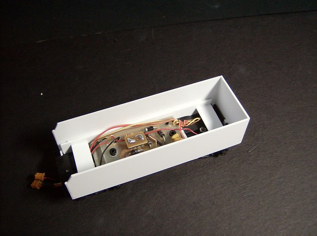
Once the two side pieces are made you can glue them to the built inner frame assembled in the final position using the marks made earlier 3/32" up from the bottom centering left and right at the far edges of the original frame making sure they are nice and vertical. I like using the testors red tube glue for things like this because you get a period where you can tweak the piece until it sets.


These next pictures show the inner frame with the back pannel placed glued to the back sides of the side pannels on and off the original frame.


The underside.


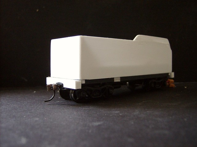
Next I added the front pieces, generally used as crew storage, in this case furthering the shell skeleton. Its two pieces cut to 1/4" x 13/16" and glued to the front edge. Also there is the top coal retailing walls which started out as 2 2/16" x 3/16" strips then held at the end of the top angle I made a line continuing the angle on the front, eyeballing it the back angle is slightly less sharp, that was one thing I just did but it fits in about 3/16" space. Both pieces are then glued to the tops of the shell sides.

Another thing added is the front and back end beams which are pieces of .125 x .188 styrene rod that I had and added a strip of .040 to the side to make them more square. They are cut to fit to the edge of the newly in position shell. One across the back with the coupler pocket notched out so the top of the beam reaches the bottom of the tender shell and two pieces on the front from the draw bar assembly to the shell edge.

You wil notice as well the shell looks more refined, once the main pieces were in place I sanded all the corners to be round being careful no to sand too far and not get rid of any glue point, even though its thin using super glue will keep it together and adding the rest of the interior walls will strengthen it again. That step can wait I just got impatient.

The administrator has disabled public write access.

Semi-streamlined G-2sa 10 years 9 months ago #1602

  • Wowak
  • Wowak's Avatar
  • OFFLINE
  • Engineer
  • Posts: 101
  • Thank you received: 8
I'll be watching this with interest, as a K-4 to G2 conversion is something I plan to do (eventually) in O-scale.
Building O-scale models of Reading steam power

brianwowak.wordpress.com/
The administrator has disabled public write access.

Semi-streamlined G-2sa 10 years 9 months ago #1621

  • Casey
  • Casey's Avatar
  • OFFLINE
  • Conductor
  • Posts: 209
  • Thank you received: 57
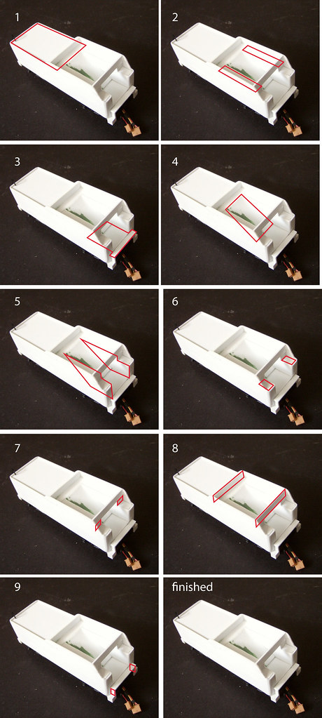
Next is building the top of the tender, when I did it I got kind of into the zone and the next thing I know almost the whole major structure top was built, but I made a step by step diagram based off of the picture of what was finished. All segments are cut using .040 styrene.


STEP 1: place the top rear a piece a piece cut to 1 5/16" x 2 1/2" I did not glue it flush with the top, I eyeballed it but it would be about 1/32" down from the top lip and glued to the back wall.

STEP 2: the extensions to create the inner wall of the coal bunker 2 pieces cut to 1 5/16" x 3/16" glued at the same height of the previous piece and butted up against that same previous piece.

STEP 3: the deck/gangway this piece needs to be flush with the front walls and extend back, I did extra for a little room for error on the slope piece in step 4. the piece is 1 5/16" in length with a T shape at the top that is 1/8" forward and 5/32" to the sides. The inside width is gotten from the measurement between the two front walls that for some reason I did't write down. That piece is glued flush with the front walls 1/4" from the bottom eyeballed to be level.

STEP 4: the slope of the bunker a piece cut to 1 1/4" x 23/32" glued to the back first step piece and then let it sit where it sits being auto centered from the pieces of step 2 then glue in place.

STEP 5: interior walls, these pieces were just cut to fit the top follows the length of the step 2 pieces then at the end of that notches down to match the height of the front walls, then is a little oversized to follow the step 3 and 4 pieces to have something to glue to. The basic shape being illustrated in the picture.

STEP 6: more shaped to fit filler a rectangle piece to create a lid on the opening.

STEP 7: the remaining filler for the opening.

STEP 8: the cross beams of the coal bunker 2 pieces cut to 1 5/16" x 3/16" one glued flush with the notch in the front the other glued about 3/16 from where the slope piece is glued to the top (it was eyeballed)

STEP 9: side pieces that will have steps glued to them sized at 1/8" x 1/4" glued to the front and the underside of the gangway.

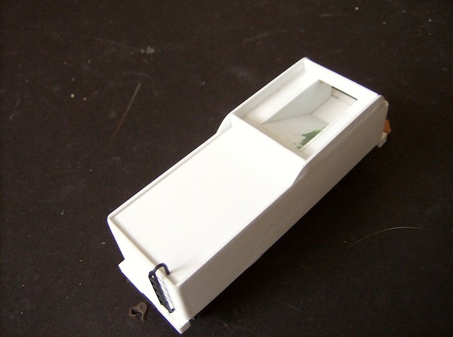
Here is another view and showing one of the salvaged pieces from the K-4 tender, the latter.
Last Edit: 10 years 9 months ago by Casey.
The administrator has disabled public write access.
Time to create page: 0.138 seconds

Today's Image

Did You Know?

December 9, 1839
The entire Main Line of the Philadelphia and Reading Railroad was opened.

Downloads

Operations Information

Click Here!A variety of Reading Company operations related documents, etc. that may be of use in your modeling efforts.

Operations Paperwork

Click Here!A variety of Reading Company operations paperwork, such as train orders, clearance forms, etc. that will help you operate your Reading layout in a prototypical manner.

Timetables, Rulebooks, Etc.

Click Here!Public Timetables, Employe Timetables, and Rulebooks that provide much useful operational information.

Modeling Goodies

Click Here!Signs, billboards, and other FREE goodies for your use.  We ask only that you help spread the word about The Reading Modeler!

Rolling Stock Reference

Click Here!Downloadable reference documents on the various classes of Reading Company Freight and Passenger rolling stock.

Thanks for Your Support!

If you find the content on The Reading Modeler valuable, won't you please consider supporting our efforts? Your donation will help to offset operating costs and acquire new material to share on the site. Thank you!

Amount: 

Advertisements