In this I will try to explain the best I can how I used an original I-10 valve gear assembly on a Bachmann Spectrum base. Over all the project worked out well, it gave me way more problems then the I-8 did, just from some bad luck, things gluing when they weren't supposed to and plastic breaking on me.
The starting point is my I-10 which in this picture still stock spectrum.
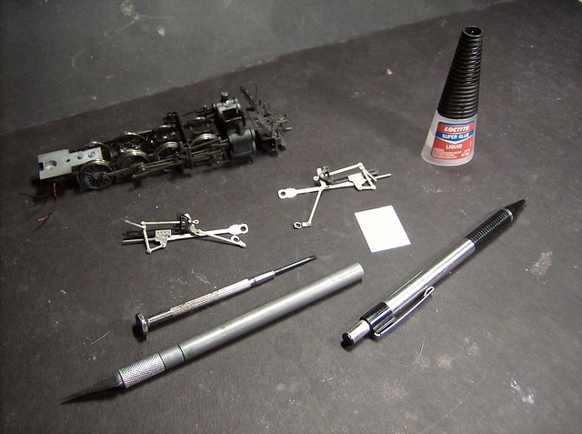
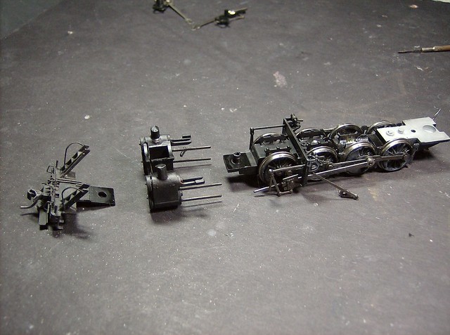
To start get the engine down to the frame, no lead truck, shell, or motor mount is needed and the locked gear would get in the way of making sure it rolls free. Be careful of taking the plugs off the tender of course the wire ripped out as I got this ready so I had to tie them back without the plug when I reassembled it, sigh. The picture also shows basically what was used to do the conversion. The white square is a scrap piece of .010 styrene.
I used a dremel as well to grind down the rivets sticking out of the back of the crosshead. The light washed out what I was trying to take a picture of, but lightly grind them down and add a little glue so it stays together, make sure the glue doesn't seep into the crosshead guide and lock it together. Just that happened to me on doing this and I just rebuilt the one arm of the guide with a piece of .025 rod and glued it where the plastic would have been. Also the plastic rod molding off the link hanger facing up toward the camera get cut off flush to the main casting that goes down to make the crosshead guides.
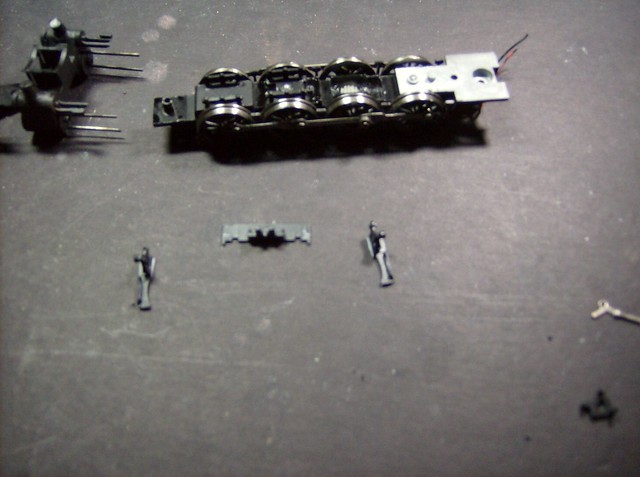
On the actual frame the cylinders and pilot sit on a rod molded into the frame that the screw to hole the motor mount goes threw. They just lift up. I also unscrewed the eccentric crank, DO NOT LOSE THOSE SCREWS, they are small.
One screw holds the yoke with the rods attached.
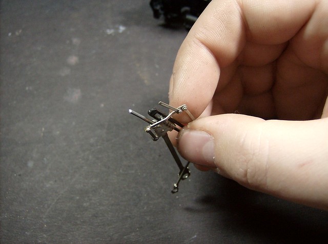
A little blurry but then pull the outer sides of the valve gear hanger off. Its two pieces but if it breaks no big deal it's getting discarded anyway.
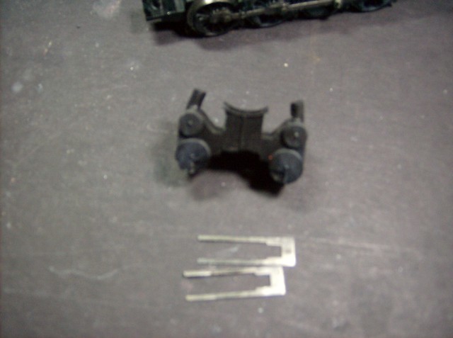
Cut the piece at the same spot on both sides on the inside wall of the valv gear hanger right at the brace triangle molded into the piece. The bracer triangles also get cut off.
To get rid of the original crosshead guides, the cylinders just pull apart. They are not glued its just a friction fit. Then you can spot the crosshead guides from the inside and just use a pair of pliers to pull them out then push the two halves of the cylinders back together.
Getting close to a test fit, but a few things need to be done. On the piston rod off the crosshead you will need to cut about 1/8" off it so it does not hit the front cylinder heads in the in stroke. You will also see I put an S shape on the vertical rod right below where the rod for the upper piston valve goes in. The spectrum cylinders do not angle as far as the original ones so it is to account for that and not make it bind. At the bottom of that vertical rod I used a dremel to grind down that joint just a little. It's a close clearance so its to ensure the movement does not hit the cylinders which would cause it to bind. All is done to both sides.
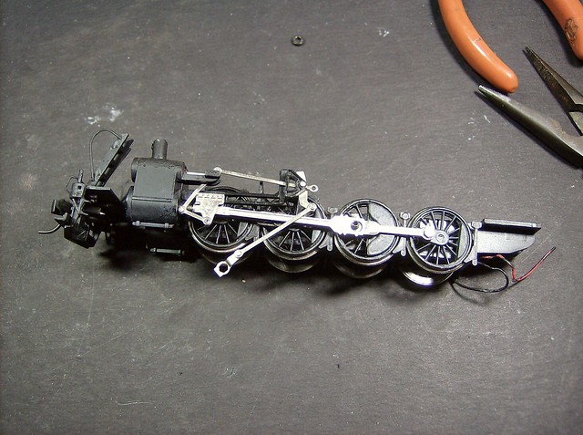
This shows about where everything will sit besides the plastic mold of the crosshead guides and valve gear hanger which will sit more forward. The Hanger will get glued to the trimmed yoke that is screwed back into place. At the time of the picture I was testing to make sure the cut I did on the piston rod off the crosshead would work. In this when in doubt cut so it is a little long and trim back in small increments until it fits.
The original bearings off the drivers were bigger then the spectrum ones so they need to be reset. You do this by filling the holes with styrene and redrilling them. I set the rod flat on the styrene and trace the hole with a pencil and cut just a little outside the line to account for the shift. Styrene will smush into the metal shape if you do that use the flattened areas as a guide to cut then glue the pieces into the holes. Then drill the main rod to fit the bearing off the driver toward the front and the eccentric crank to fit the screw that came off the driver. The picture shows one drilled one not.

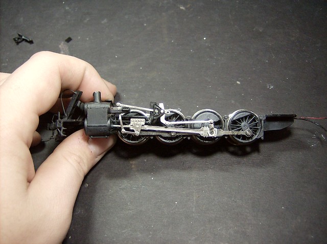
Then cut the front of the crosshead guides The total length was around 7/32" but start smaller and trim small. At this point its a lot of putting it in and testing it, just the main rod. Like I mentioned earlier you want the hanger to line up with the original yoke. Hold the hanger in place with your thumb and roll the wheels with the other hand. Once satisfied with how it rolls glue in place to the yoke and the cylinders. Put the spacer back in the driver to space the mairod and the side rods and screw the whole thing together.
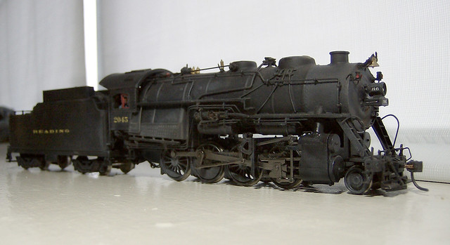
Repeat for the other side, make sure the whole thing rolls well then reassemble and you are ready to go.
Also here is a Video of the completed conversion running pulling not so prototypical hoppers but it looks good and only being 13 cars I really need to replace the trucks, they do not roll well so the engine is under a good load.
www.flickr.com/photos/60361449@N02/11499...t-72157638919840634/ 


 A variety of Reading Company operations related documents, etc. that may be of use in your modeling efforts.