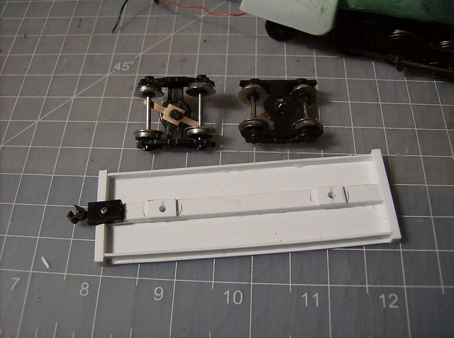
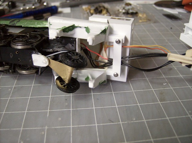
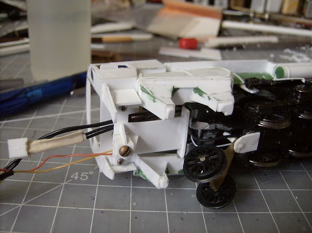
The tender frame was started as the top flat piece which is a cut piece of .040, I got my width from measuring another tender frame. The end beams were then placed which is a styrene bar the same thing I use for pilot beams. The sides are pieces of .040 cut to fit in between the beams. The center beam is 3 layers of .040 with an extra .040 pad to lift the frame from the truck a little. I measured the center and drilled holes for the screws that came with the bachmann spectrum tender, the electrical guts are all reused basically as they were designed. The trucks got the clips cut off so they are flat on the bolsters then drilled in the center for the screws.
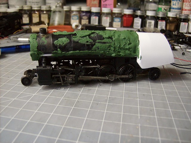
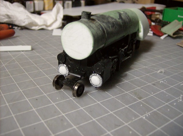
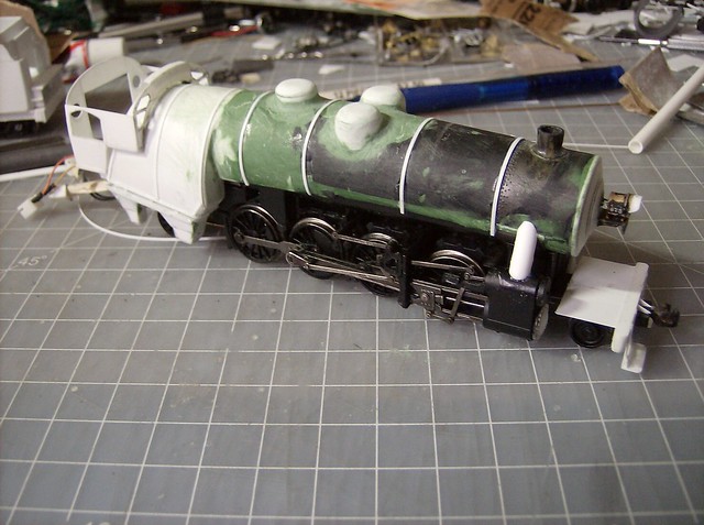
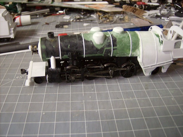
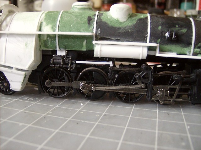
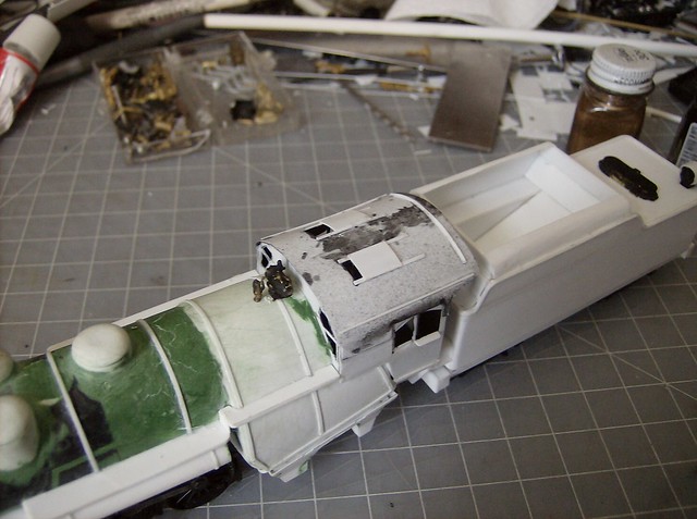
Since there was no pilot in the way yet I did the cylinder heads made from a shaped piece of .040 in a dome and a bunch of squares cut from a .020x.010 strip of styrene. The putty on the shell was sanded at this point.
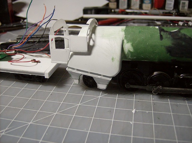
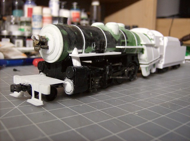
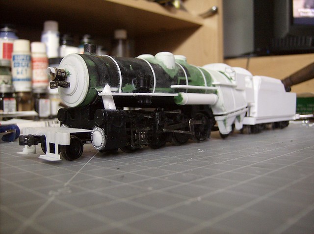
Then I made the pilot and set the base of the smokebox front which is layered the same as the E-5 with shaped .040 separated by a .010 layer. The pilot is the beam stock and the steps are done with .010. I use a dremel to carefully grind out a notch for the coupler pocket. The back of that pocket mostly got cut off for the front truck clearance.
I drilled out the headlight casting to fit the led that was on the spectrum engine, so this one will actually be led lit.
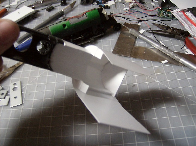
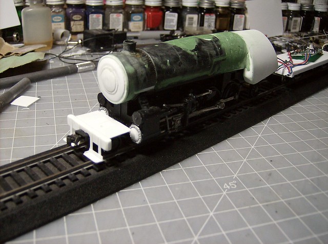
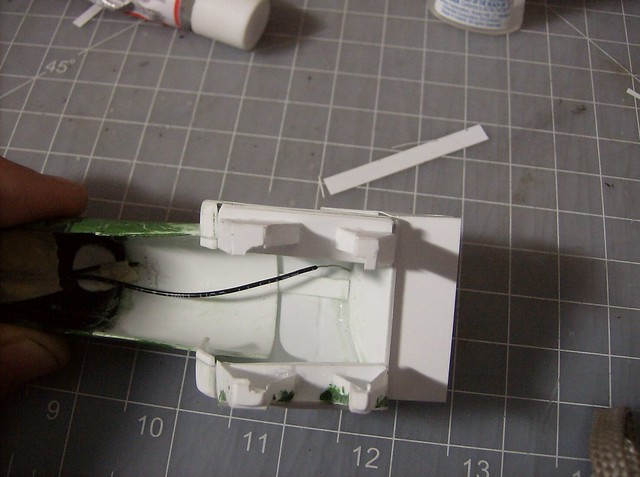
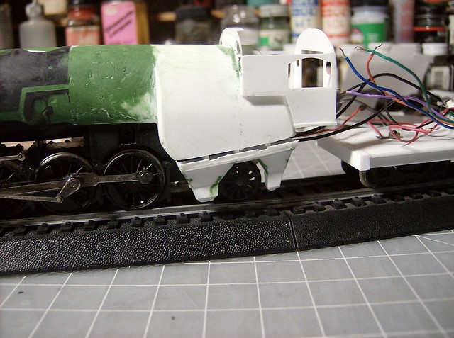
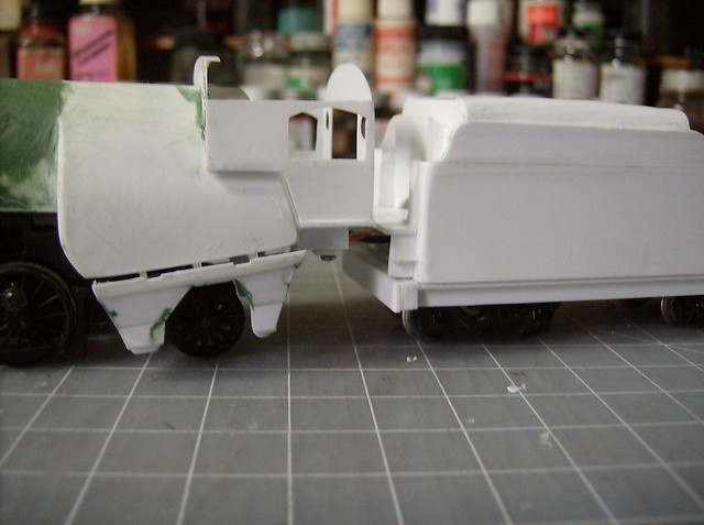
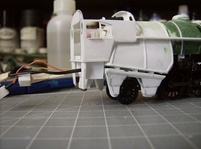
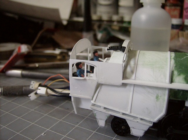
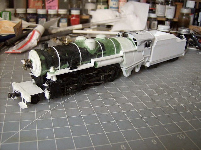
The cab is made from .010 with a .040 floor. Lehigh Valley had odd cabs on a lot of their end cab engines with the bend inward in the middle much like what is seen on european engines especially american exports. To do this I cut a little away from the front and back walls and put a nice bend line on the cab side walls to retain the shape in unsupported areas.
A little trick with cabs is if you cut something uneven you can shim where needed with scrap .010 to get it to match seen in this picture on the front wall. Also this was the first ash pan built, which was a lot of little pieces, but it turned out well and took process pictures on the other side matching what I did.
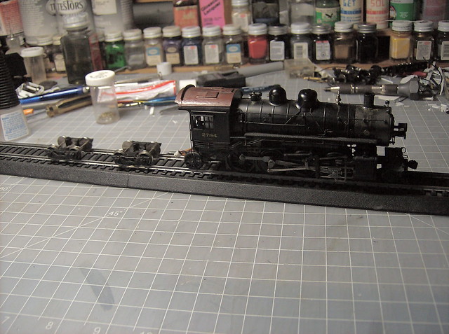
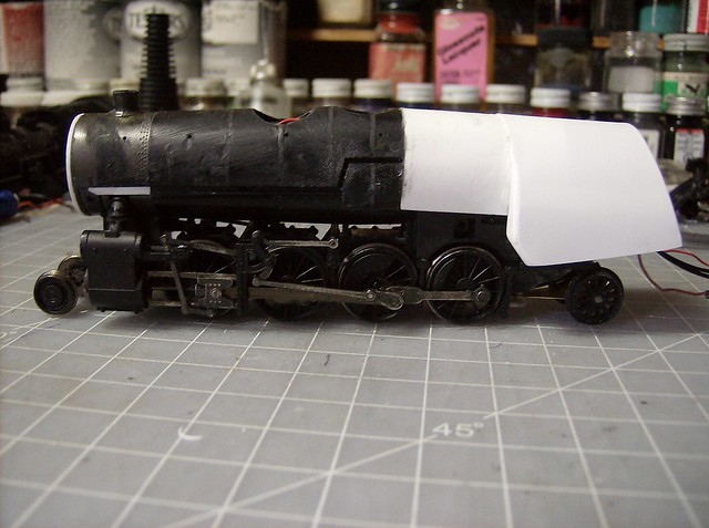
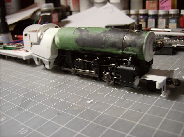
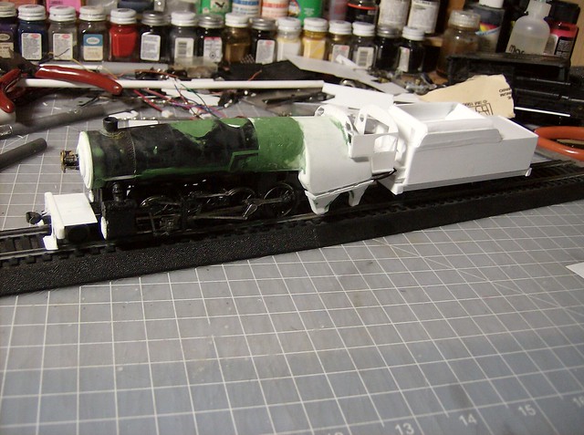
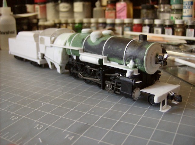
This is what was seen at the Reading Modeler Meet.
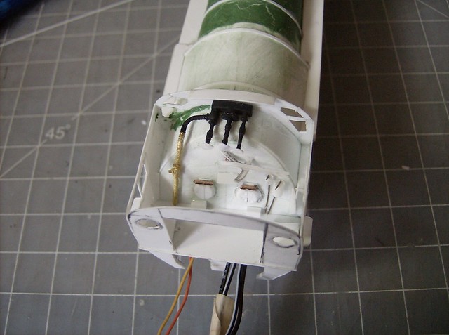
I thought I had taken more pictures then I did, but I will try to explain It starts with small pieces of .040 double layered to make the spacers, normally I only do one layer but these are made deeper and built back up. A piece of .040 is then places on top to make the base of the pan. The outlets are made from .010 the ones being attached in the picture were just copies of what I had already figured out. When learning on the fly I did the strips first for the front and back (of the engine) used testors glue so it was malleable and got the angels I like while checking the rear wheel clearance. The outsides are the full width of the pan the insides are a little thinner to make turning room. Once the frame was set I capped it with another piece of .010.
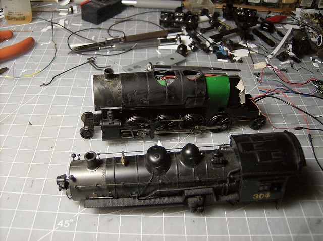
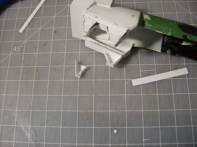
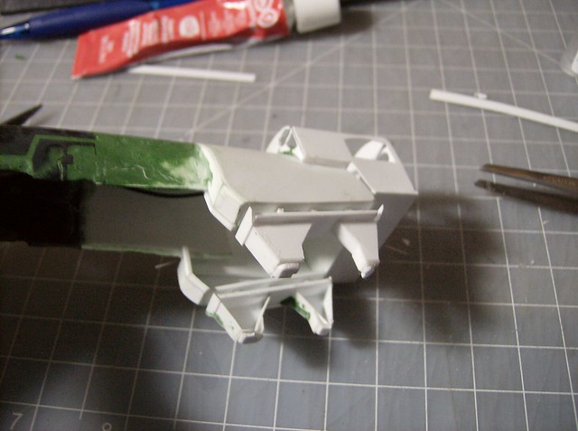
This image shows the differences in thickness and the placement left to right, also the notches on the bottoms for turning clearance, they don't have to be too pretty because you won't see them.
I shaped pieces of .040 as the bottom hatches of the pans on the front and back of the top of the pan where is a piece of .010 that is a basic frame for the 2 pieces of .010 that bridge them, it kind of curves up.
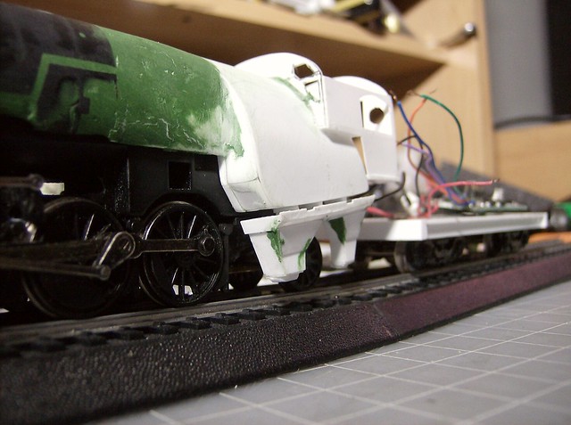
With those 2 pieces now set, which the top one has notches cut in it as access for metal rods used to push ash out or to the lower part of the pan, the bottom 2 parts angle out to the upper part of the pan. The gaps are filled with putty.
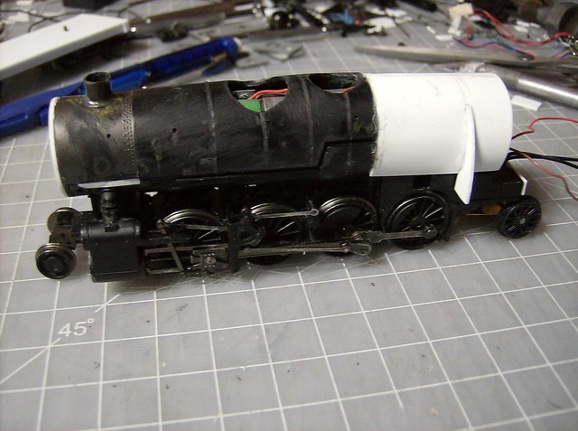
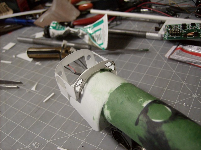
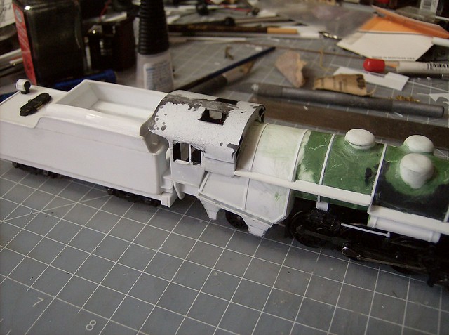
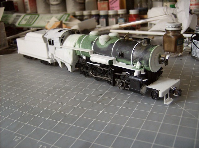
And an over all shot of that point.
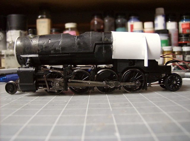
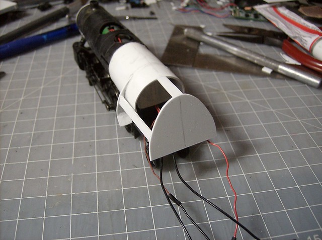
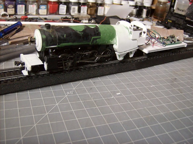
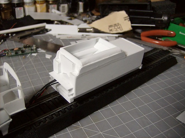
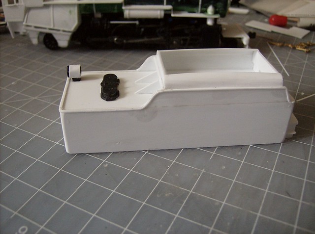
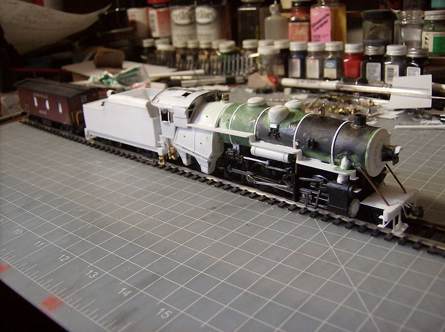
Today was building the tender shell, since the cab floor is in place we know where the gang way goes. It was done in one sitting built mostly from .040 much like the G-2 build just shaped differently. The coal bunker extension is .040 front and back walls with .010 rolled up on the sides. Theres a bit of super glue that needs to be sanded down too on the side seam done on purpose as a quick light filler.


 A variety of Reading Company operations related documents, etc. that may be of use in your modeling efforts.