FacebookTwitterDiggGoogle BookmarksRedditLinkedinRSS Feed
Welcome, Guest
Username: Password: Remember me
This section of The Interchange provides a space where members of the Reading Modeler community can showcase their Reading modeling efforts. If you've got a project that you'd like to share, start a new topic and "show and tell" the group how you did it!

TOPIC: Modern D-8 Camelback Build

Modern D-8 Camelback Build 8 years 4 months ago #5002

  • Casey
  • Casey's Avatar
  • OFFLINE
  • Conductor
  • Posts: 209
  • Thank you received: 57
This is a project I have been wanting to do for a while, but with the work done so far I'm glad it waited getting more practice first. I chose the later version because I like the way it looks and I try to not have a huge time range in the roster. The earlier D-8s with slidevalves would be easier to make as another option.

The starting point is a roundhouse 4-4-0. I managed to pick up an Athearn release one with a better motor saving some time effort and money not having to try and repower. The plan for using this model came with some research. The base options for 4-4-0s that are the easiest to get a hold of are Roundhouse (still somewhat rare), IHC and Bachmann.

I shied from Bachmann since it has relatively small drivers a rather low set boiler that would be really hard to lift up and the back of the frame sticks out pretty far for a camelback.
The IHC version would be the second choice but the running gear would likely take more work to get right plus big flanges.
The Roundhouse version has decently sized drivers, has a heavier metal frame, the rear driver sits pretty far back on the frame, and comes with spoke lead truck wheels. So over all the Roundhouse model had the most of what I was looking for.

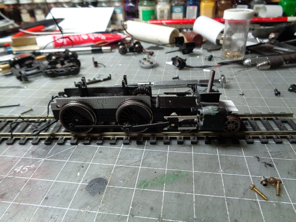
This is the model I picked up minus a couple minor details I took off when I got home with it. Gotten at a decent price but was kind of beat up and the shell shows some zinc rot. To me none of that matters to me but the seller doesn't need to know that and its stuff to look for when you are trying to talk a price down.


After the tear down the first thing to focus on is getting the running gear looking right and rolling right. I am also a believer in the don't throw out any parts philosophy and everything used for the running gear re-work is from the parts box.

Everything was made and tested in sections. First was the cylinders, crosshead and guides. The cylinders are Mantua 0-4-0/0-6-0 cylinders, the crosshead is left over from a camelback frame and the crosshead guides are from the same. I use the original main rod and riveted the crosshead in place, available from bowser. Once all in place I made sure everything rolled freely.


Side note: The pilot is gone because the front of the frame I had looked a little bent and I tried to bend it ripping off the pilot I was only going to get rid of any way.

Then I marked far rear position of the crosshead and used a dremel to trim the guides down.


The stock method of holding the rods on the wheels are plastic pins that just push in. I wanted to replace that so I could secure an eccentric crank. In the parts box were more mantua parts. Planning to use the rod spacer and screw 2 things had to be done. The back of the original main rod had a molded spacer that needed to be ground off and the driver needed to be threaded for the screw.

Using a technique found by accident a couple projects ago, I threaded the screw on the main driver by spreading a good amount of super glue on the screw threads and inserting it in the hole to glue in place. Let it completely dry and then carefully unscrew the screw, this leaves threads behind in the hole. Be careful to not strip it when setting the running gear but honestly it's not hard to just reset the thread if that happens. The spacer needs to sit flush on the back of the main rod and come through so the eccentric crank can be friction held by the screw like a stock mantua engine. The eccentric cranks are from a random junker Rivarossi cab forward in the parts box, mantua ones would likely work but I didn't find any.


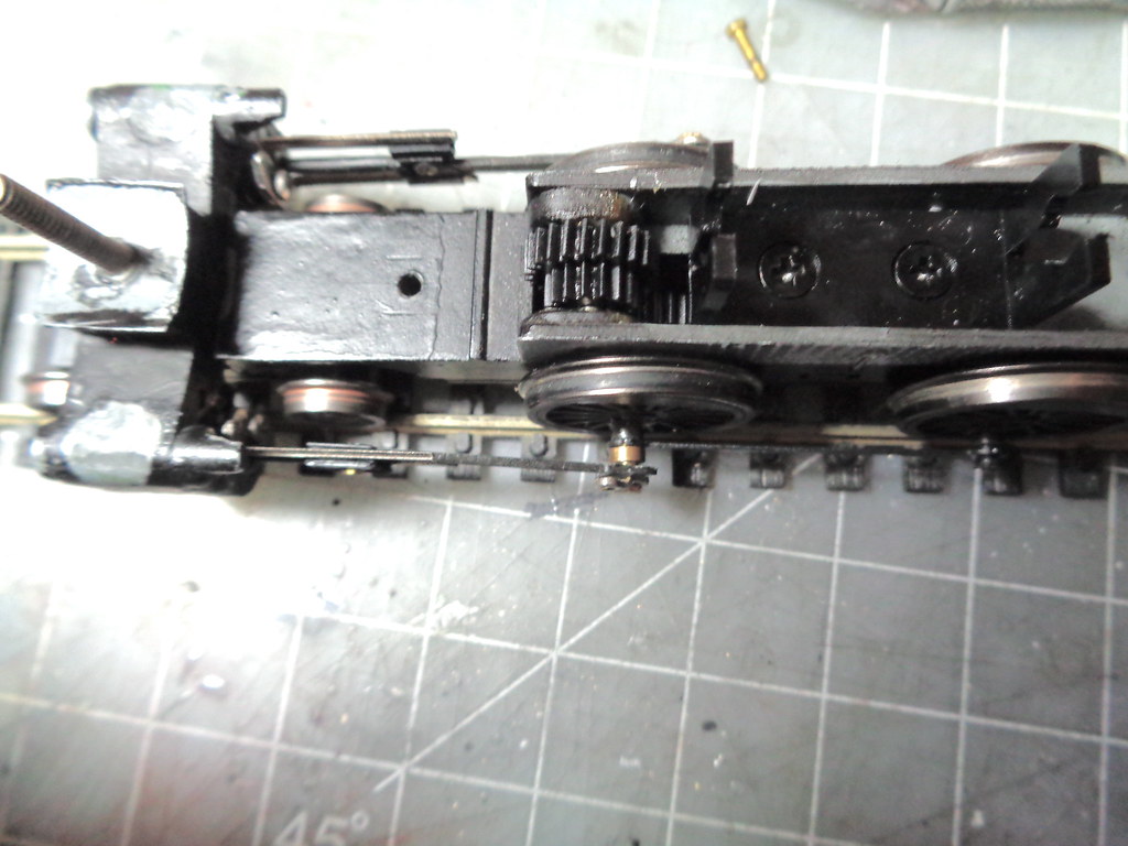
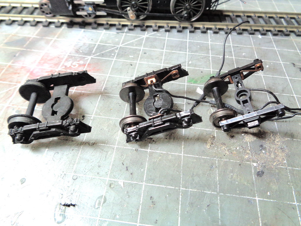
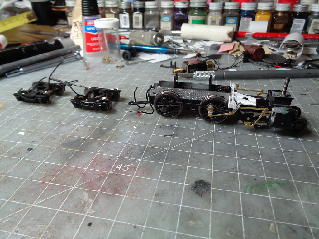
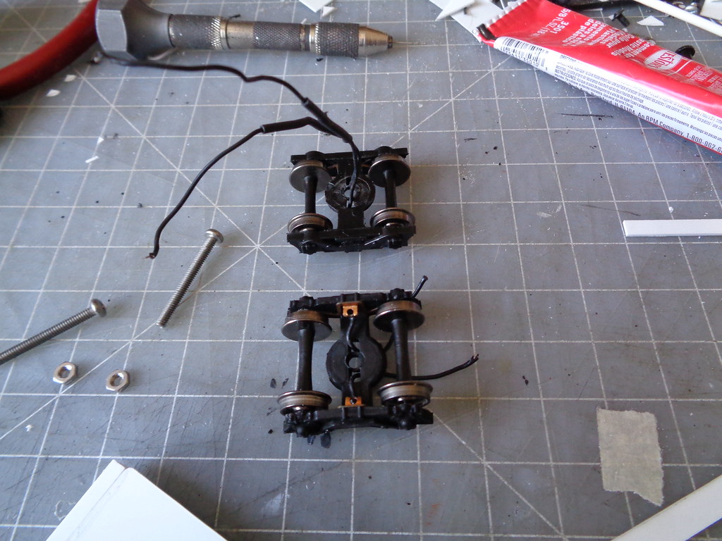
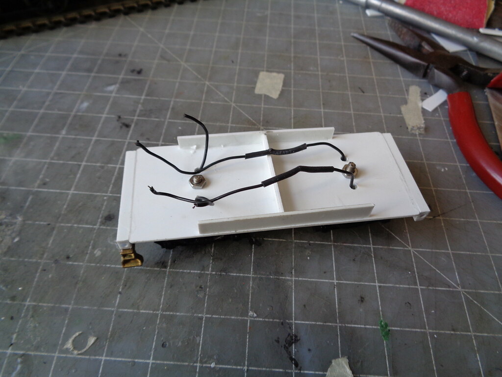
While waiting for the screws for the drivers to dry I figured out how to use the roundhouse tender pick ups on bachmann I-10 trucks. Drill the bearing holes, not all the way through, big enough for the metal bearings. Carefully take the assembly off the old truck, one per side and fit to the new holes. It will take a little bending to fit and will go in upside down. After test fitting they are glued in and the metal wheels can be placed.


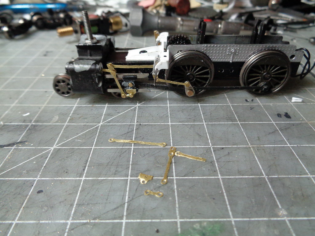
With the main rod and crank rolling smooth next was setting the eccentric rod and link, but I needed to have something to set the link on.


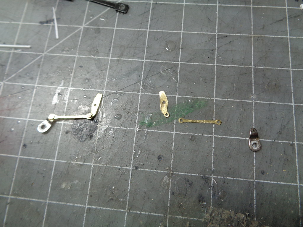
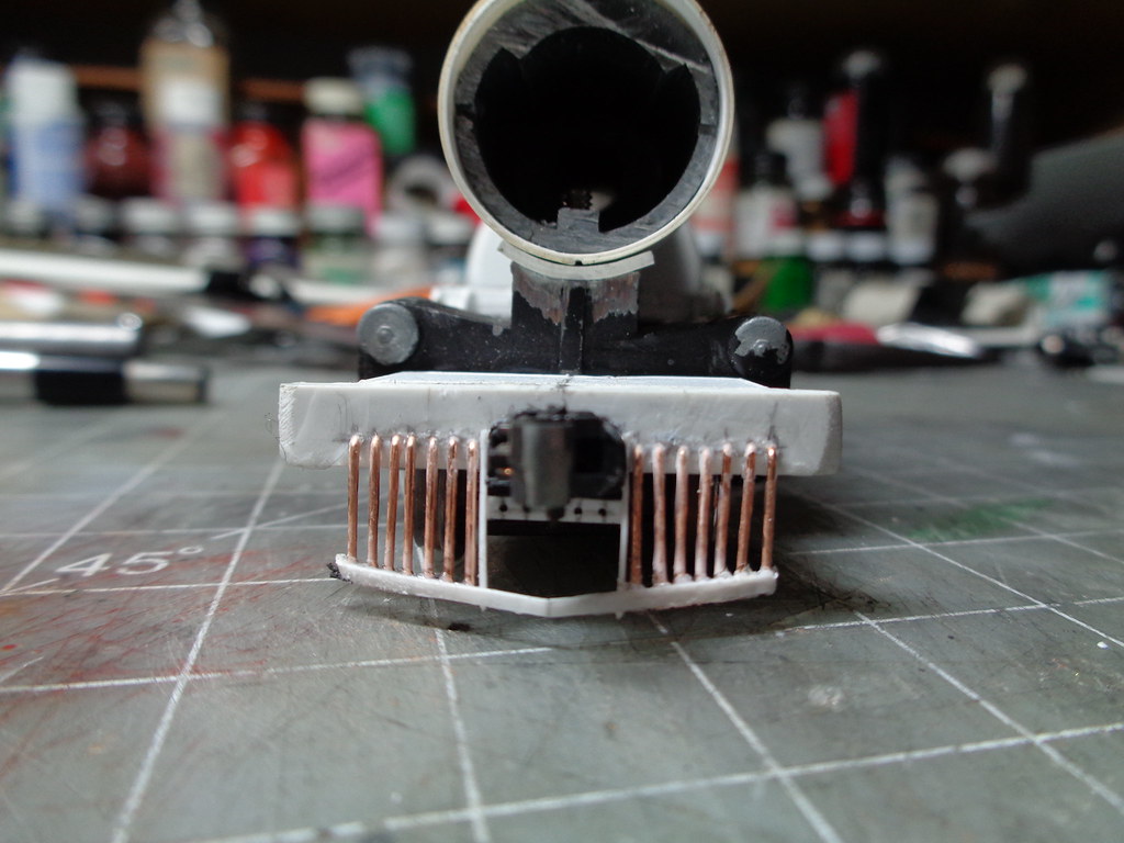
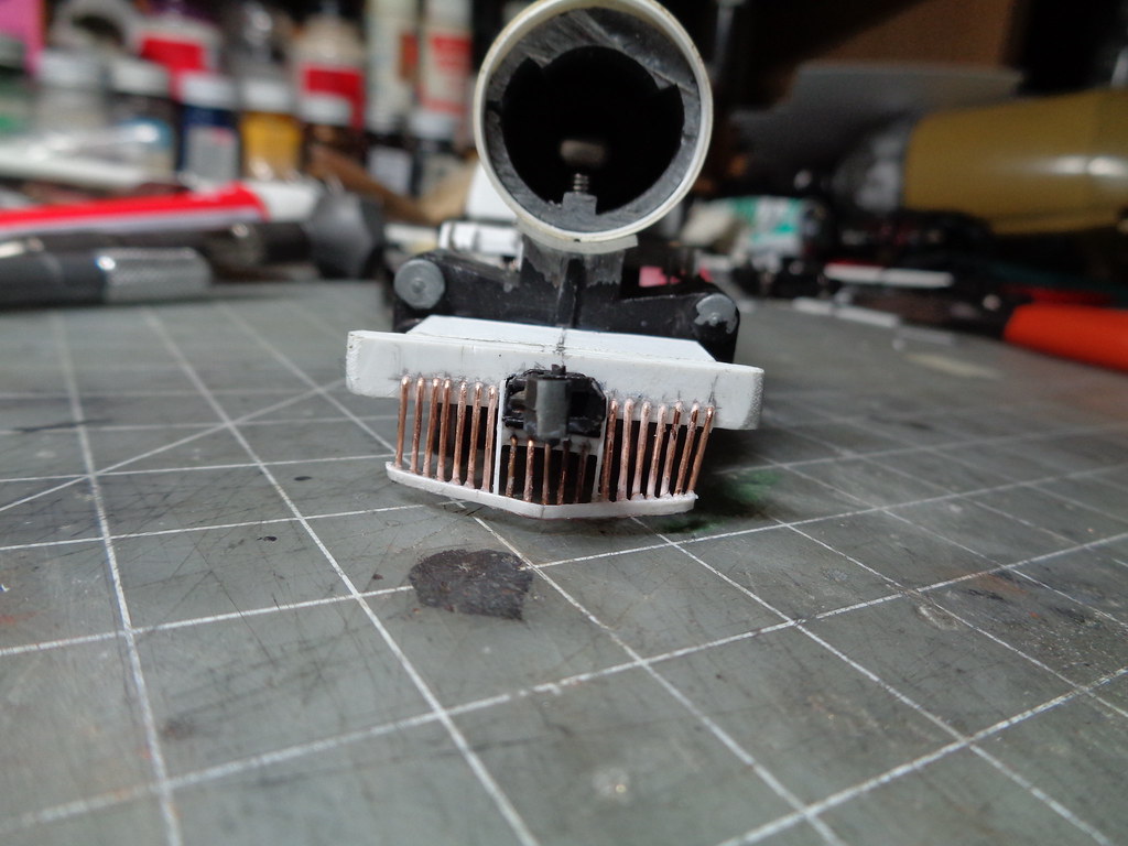
The link and eccentric rod were made from .010 brass sheet stock. The link is made from an old roundhouse link in the parts box as a template. The eccentric rod holes are spaced 1/2". When making rods I find the hole spacing and drill them, then draw the rod out around the drilled holes then cut the rod off the sheet. I use a dremel cutting wheel to get the basic shape then a diamond coated cone tip (not an expensive part) for fine shaping. This is one riveted and one in pieces.


The rods are places on the wheels and place holder wires are used to hold the link in the hanger.


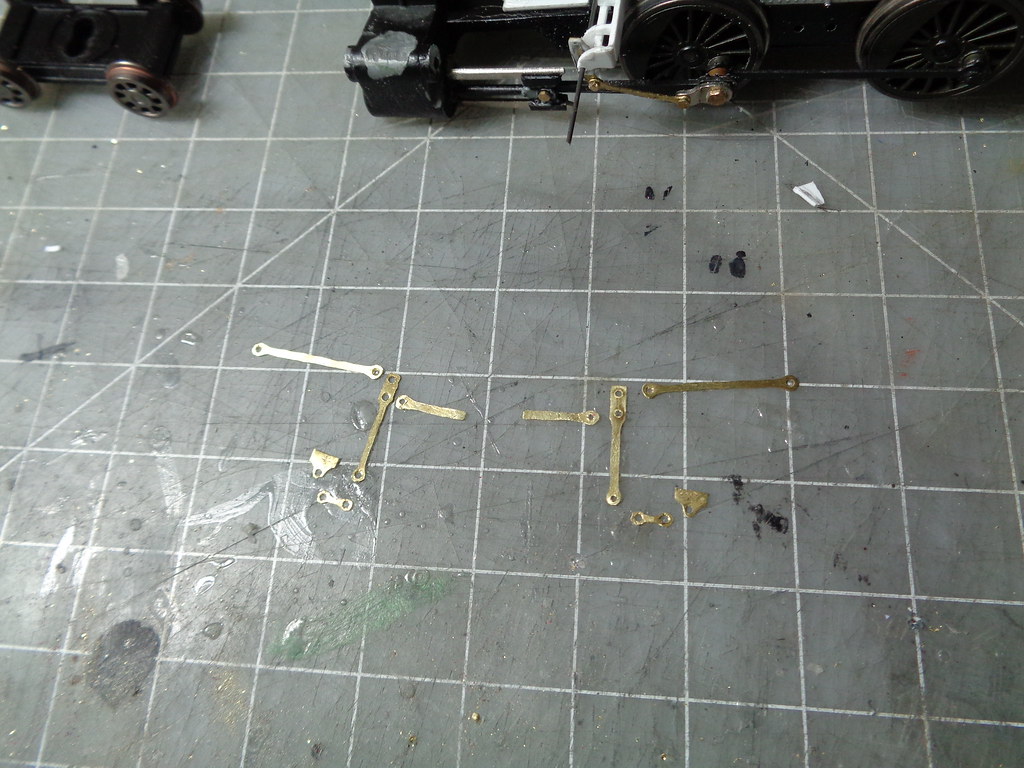
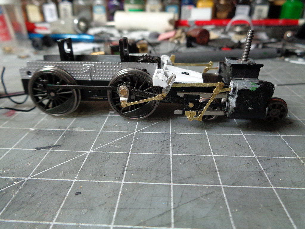
The rest of the rods was a lot of rolling the frame to see where the movement of the rods ended in the forward and rear positions, then measuring where the rods needed to be, then made from the same .010 brass sheet stock. I don't have an easy way to explain it just lots of testing measuring and checking. This is the rods pre assembly.


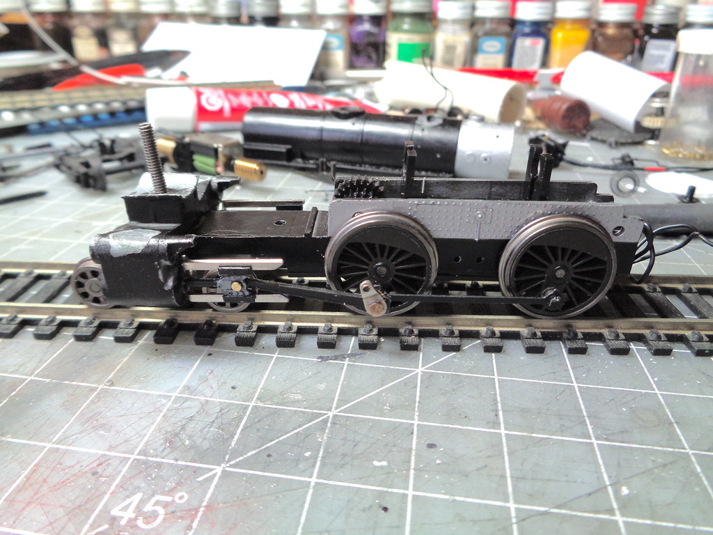
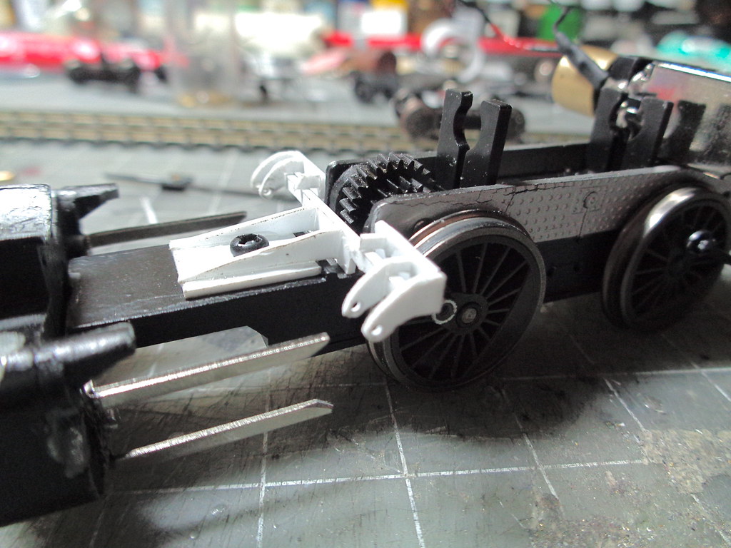
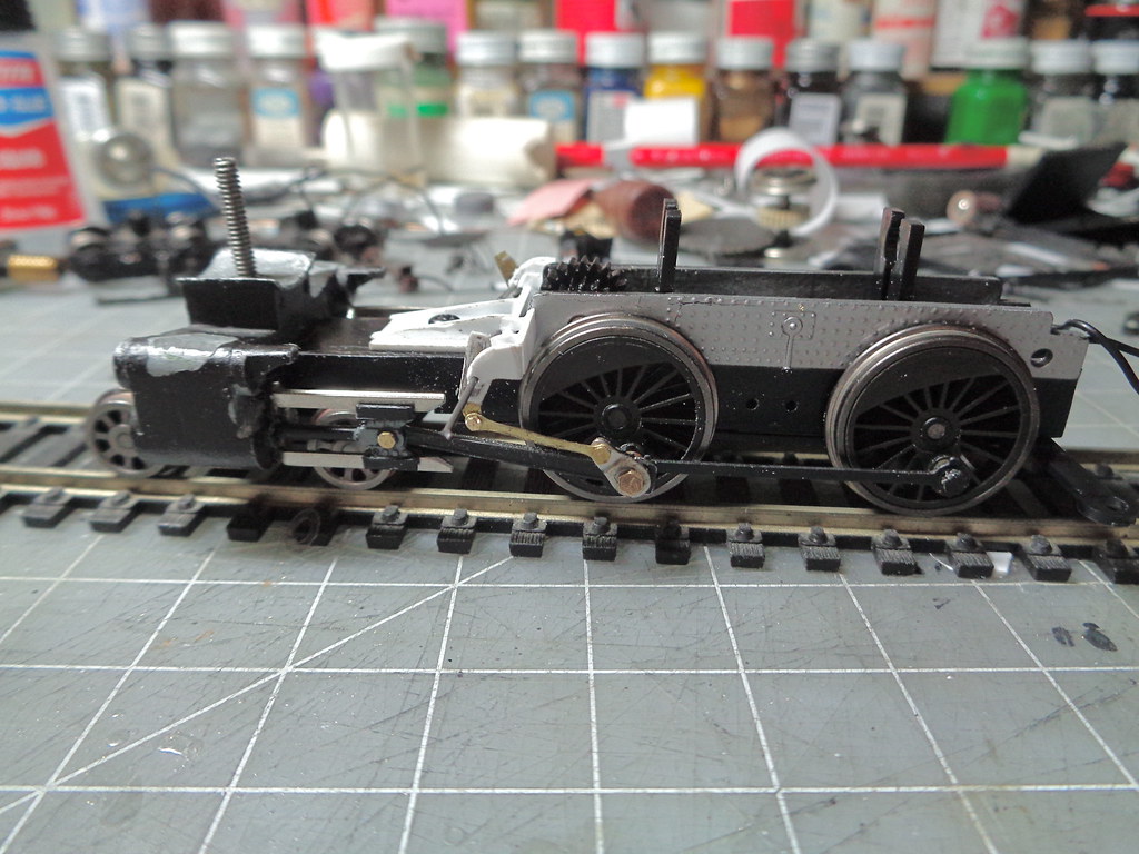
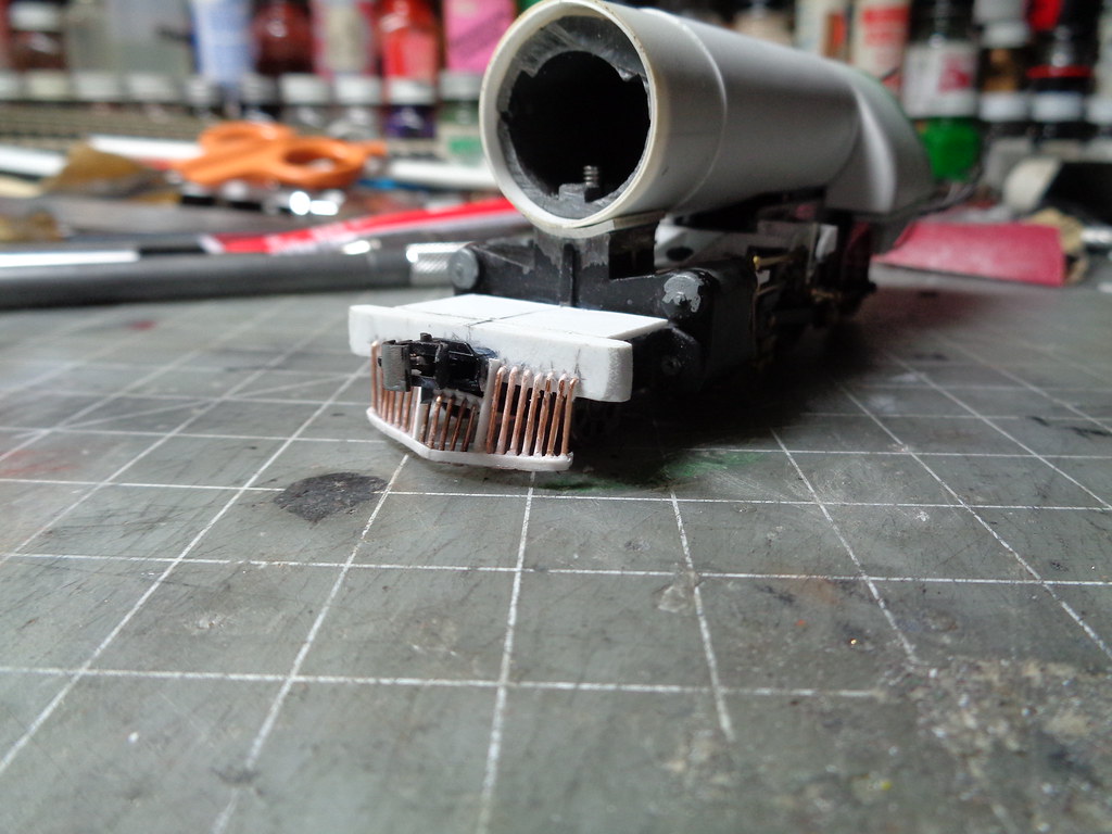
The top piston is ground to be flat on the cylinder to make room for the rods and the triangular shaped piece is glued to the bottom of the crosshead guide. All the measuring and testing payed off, once put together almost no tweaking was needed for the running gear to roll smooth.


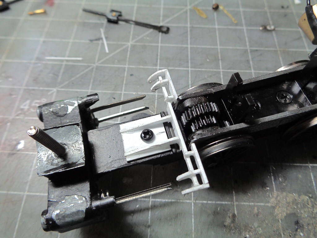
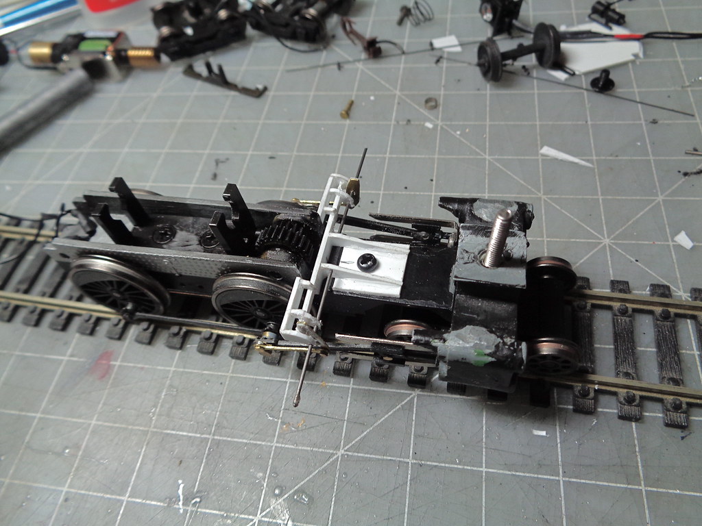
An over view of the running gear and basic wheel placement.


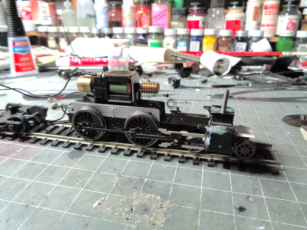
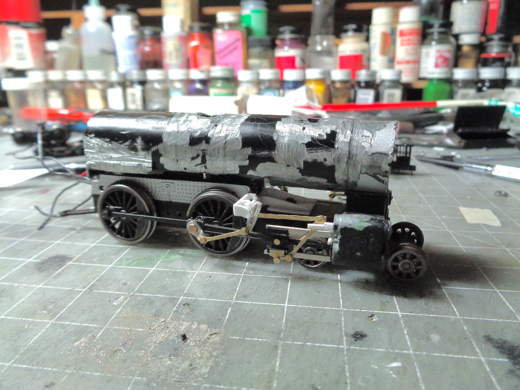
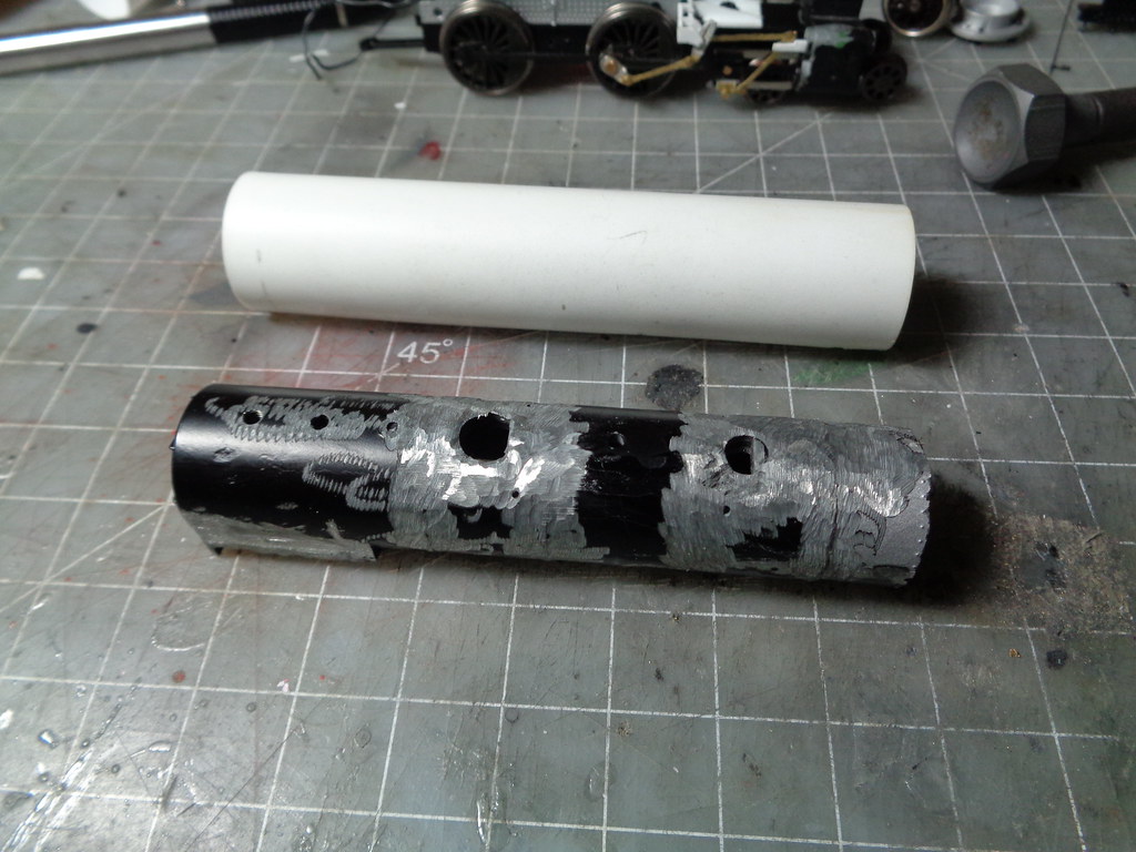
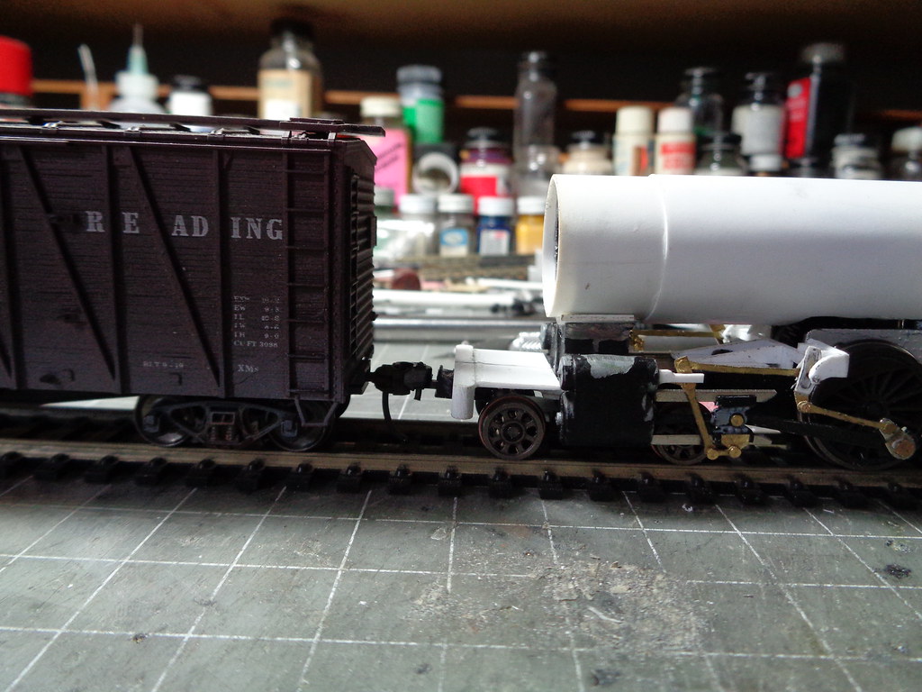
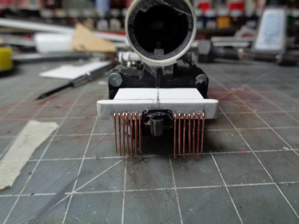
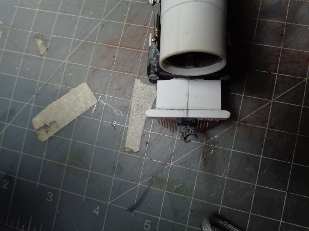
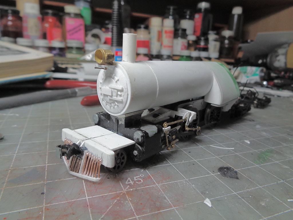
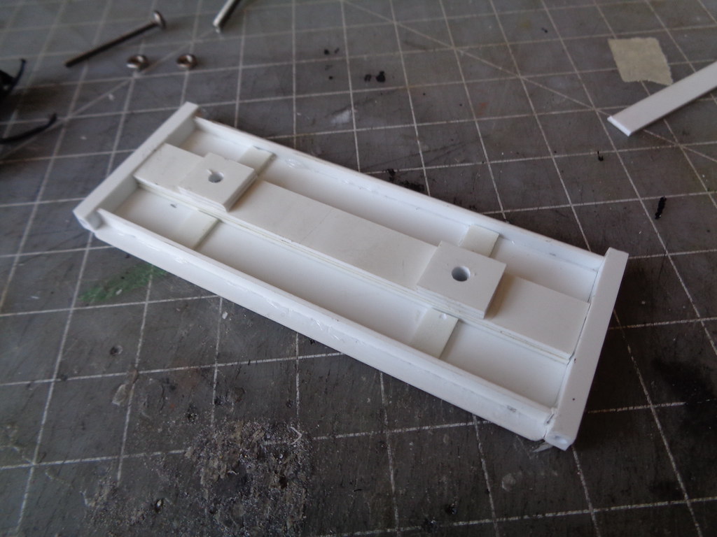
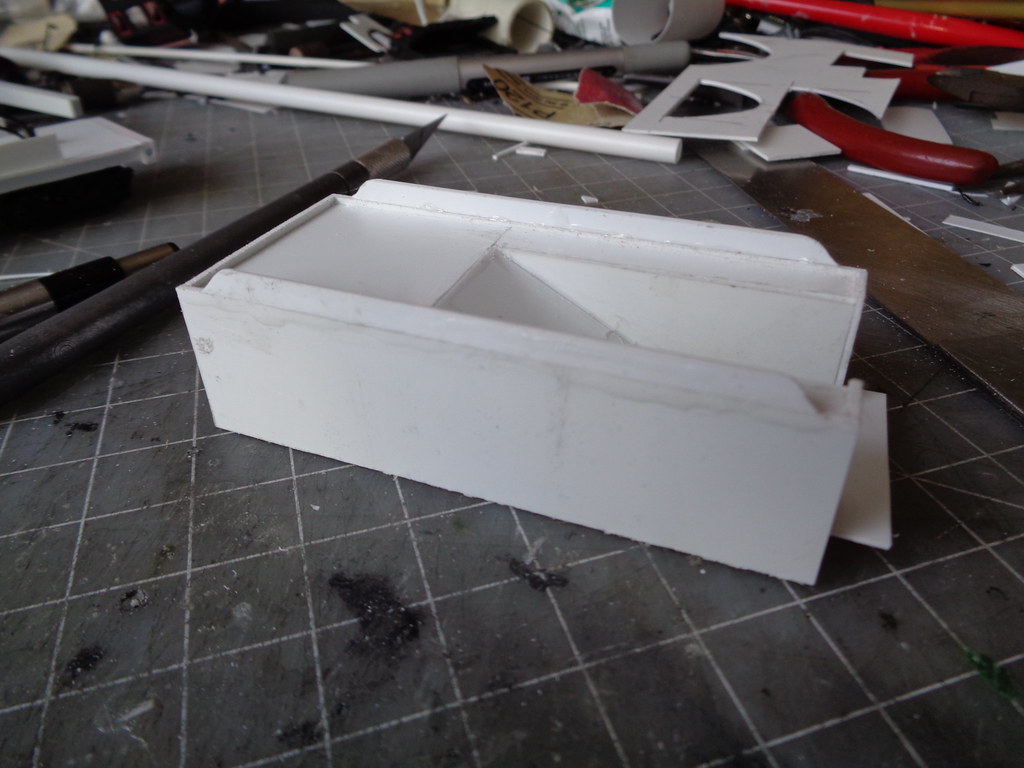
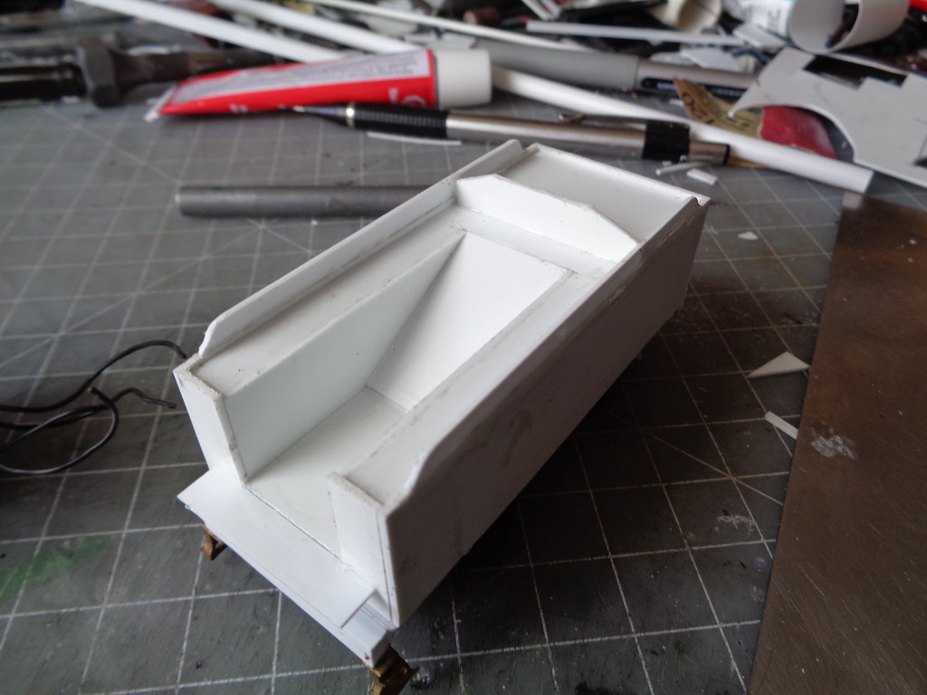
Now that the difficult part 1, getting the running gear set is done, it is time to start getting some of the other main structures built. I used a dremel to grind off all detail of the old shell as well as sawing off some of the smokebox to make space for the Reading style short smokebox. I wanted to use the base of the original shell as the weight. I'm not too worried about this engine pulling a lot since for me it's going to be on mostly passenger duties of only a few cars, the Athearn version also has a traction tire, so I'm not going to jam pack this thing with weight. Does not have to look nice at all, it is just a weight and a front screw anchor.


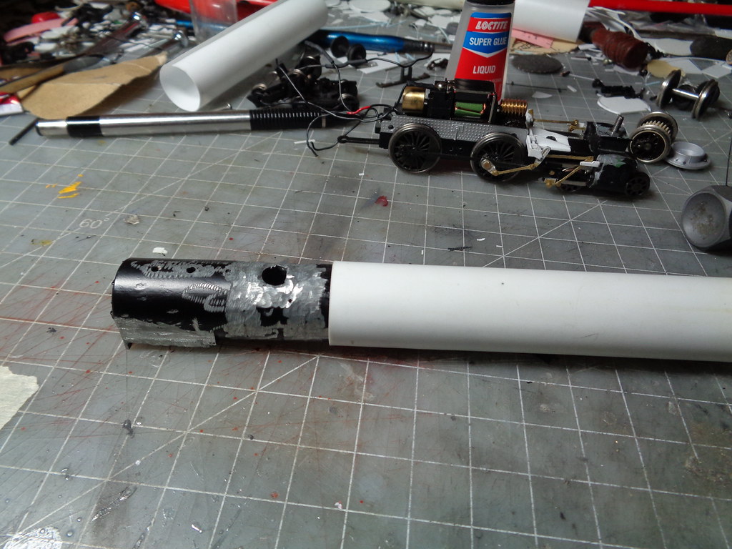
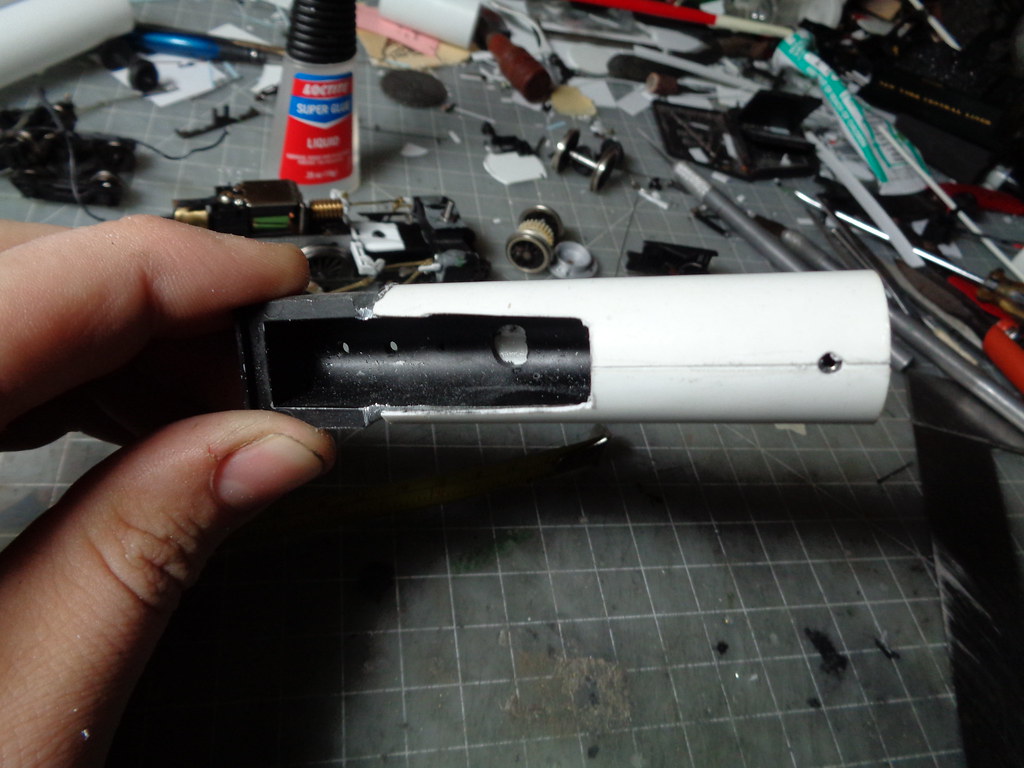
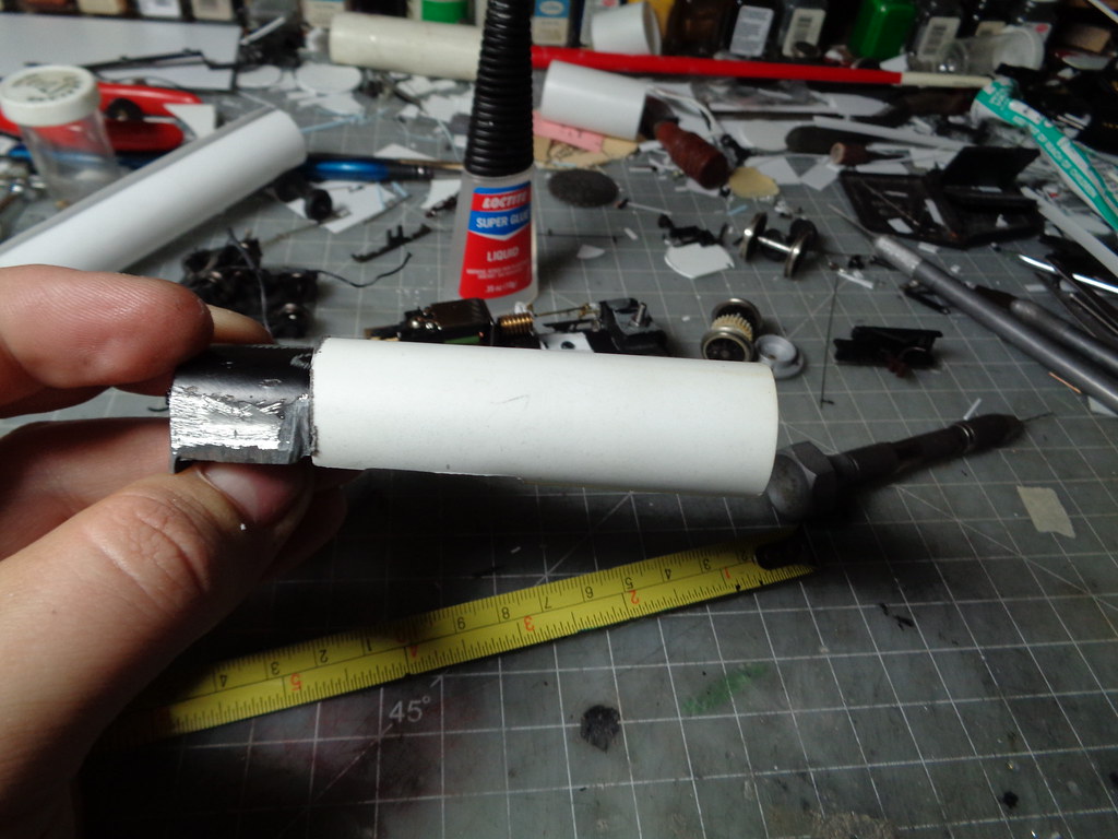
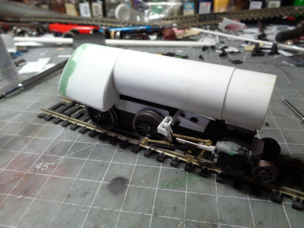
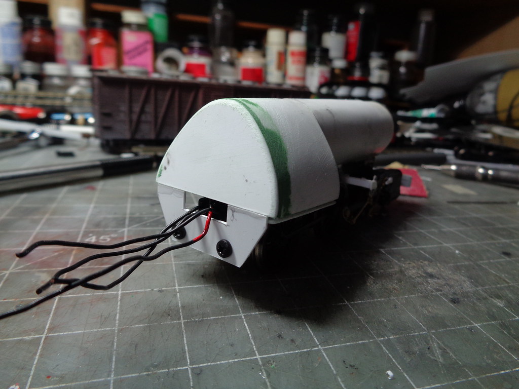
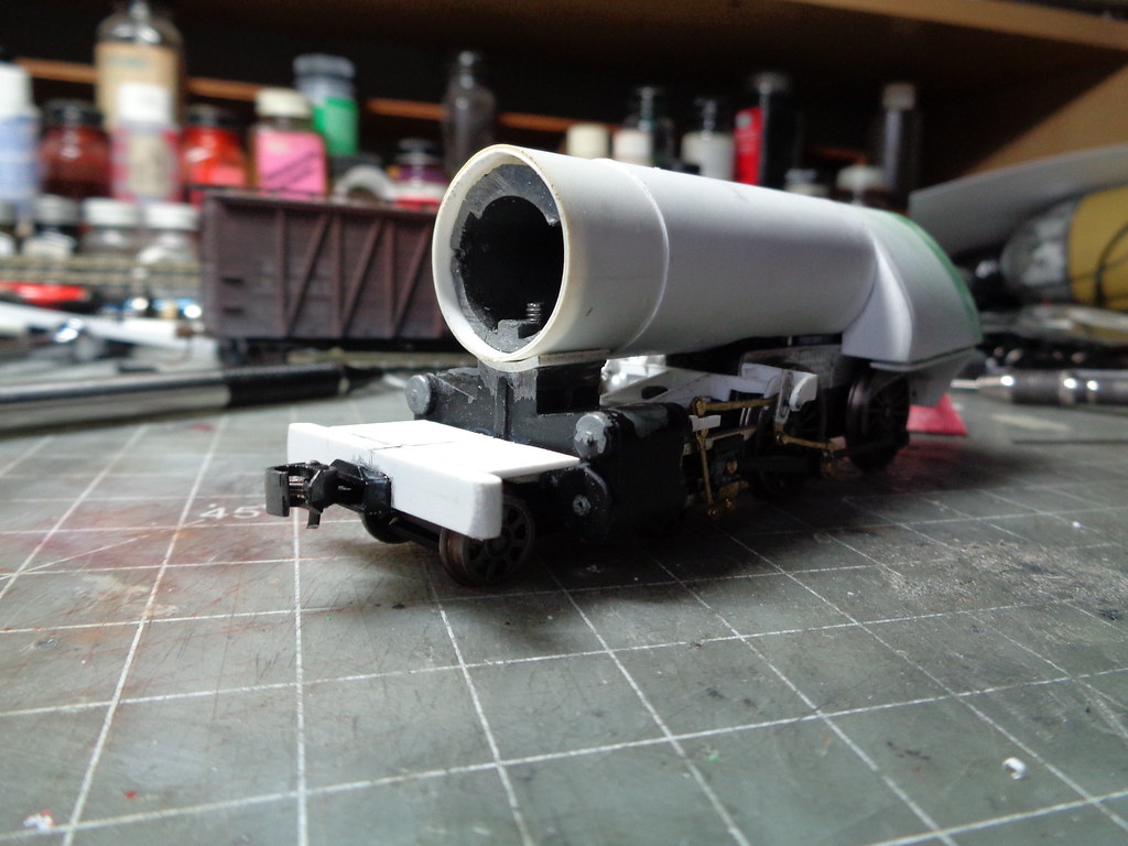
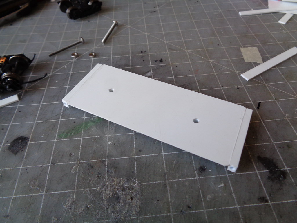
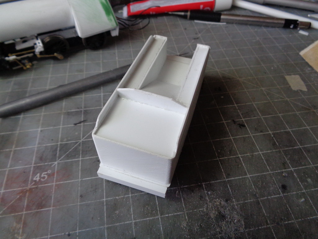
A tube was made for the old shell to snugly fit in.


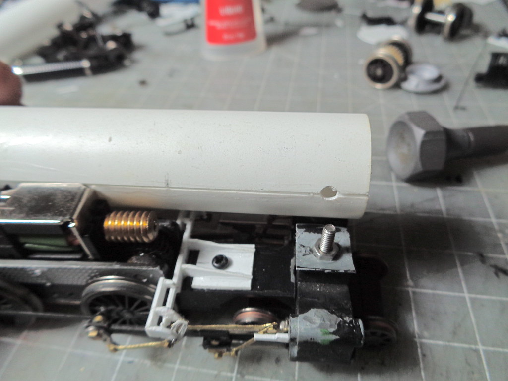
A hole was drilled setting the forward position.


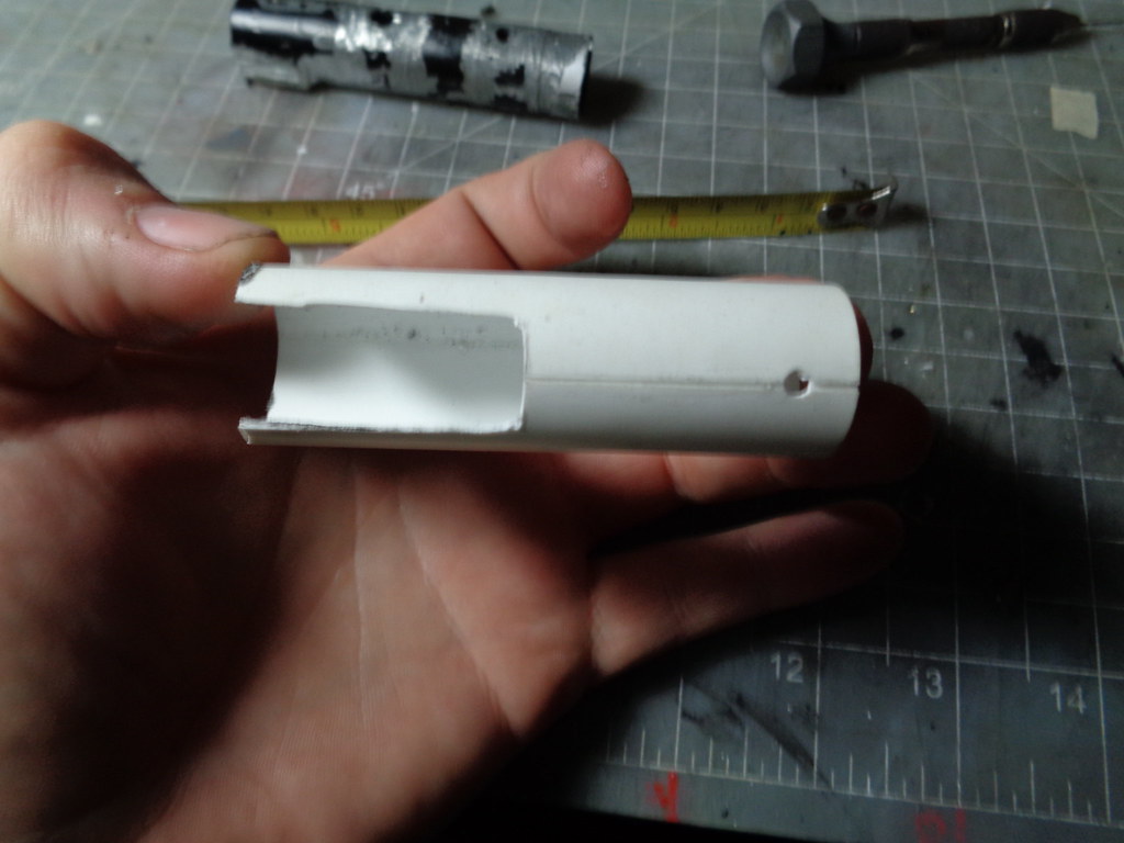
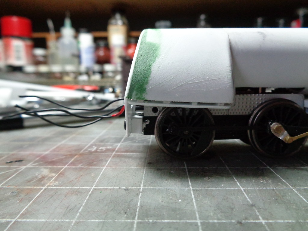
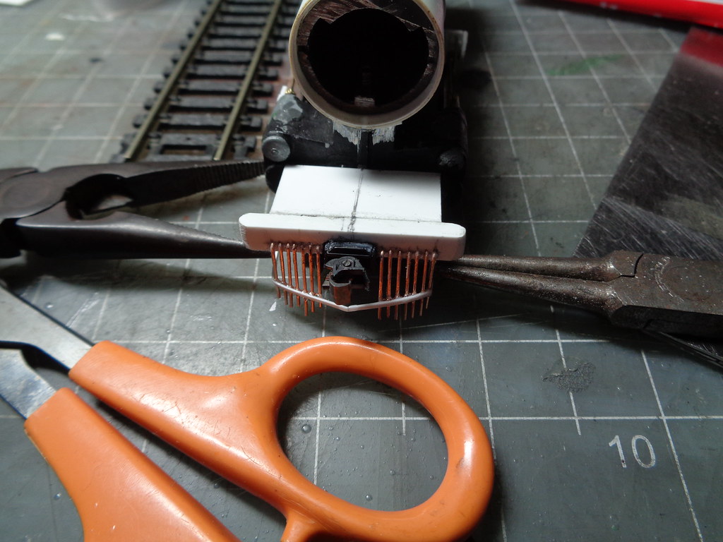
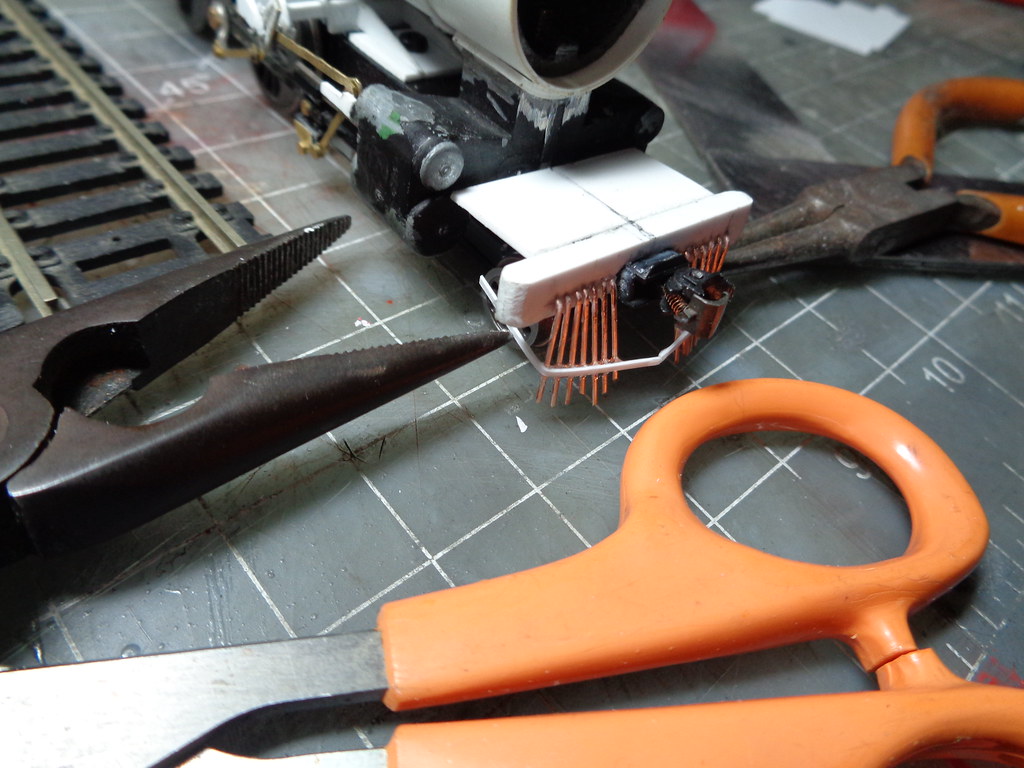
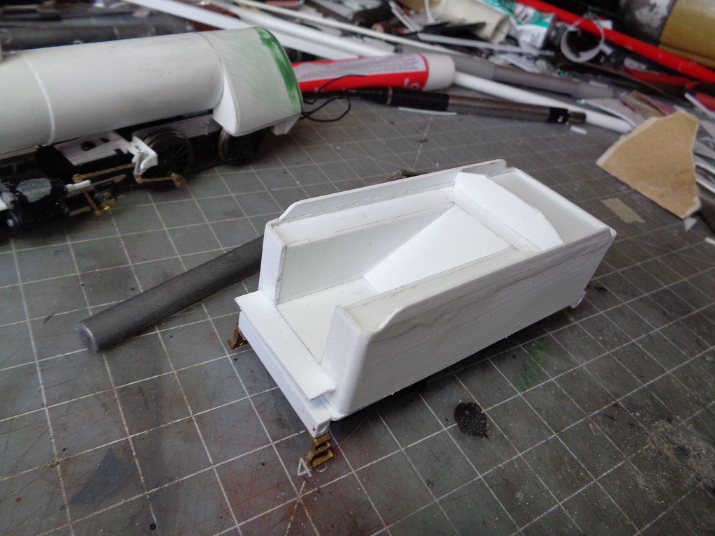
Using landmarks on the frame I cut out the bottom of the tube for the motor assembly as well as trimmed the shell to fit the old shell making sure the tube went to at least half way past the rear driver as the firebox starts before that.


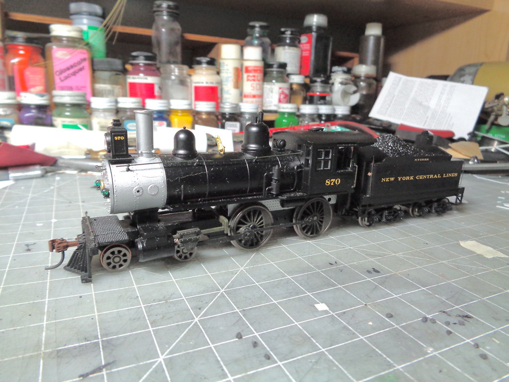
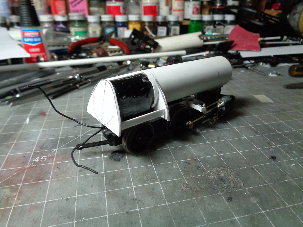
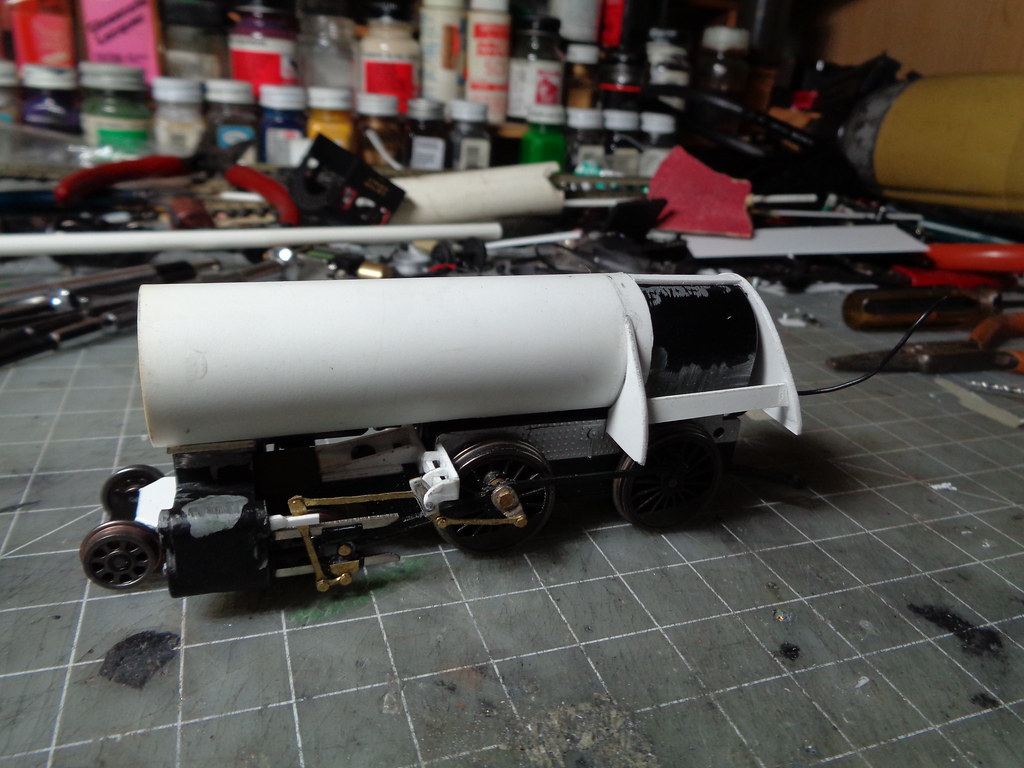
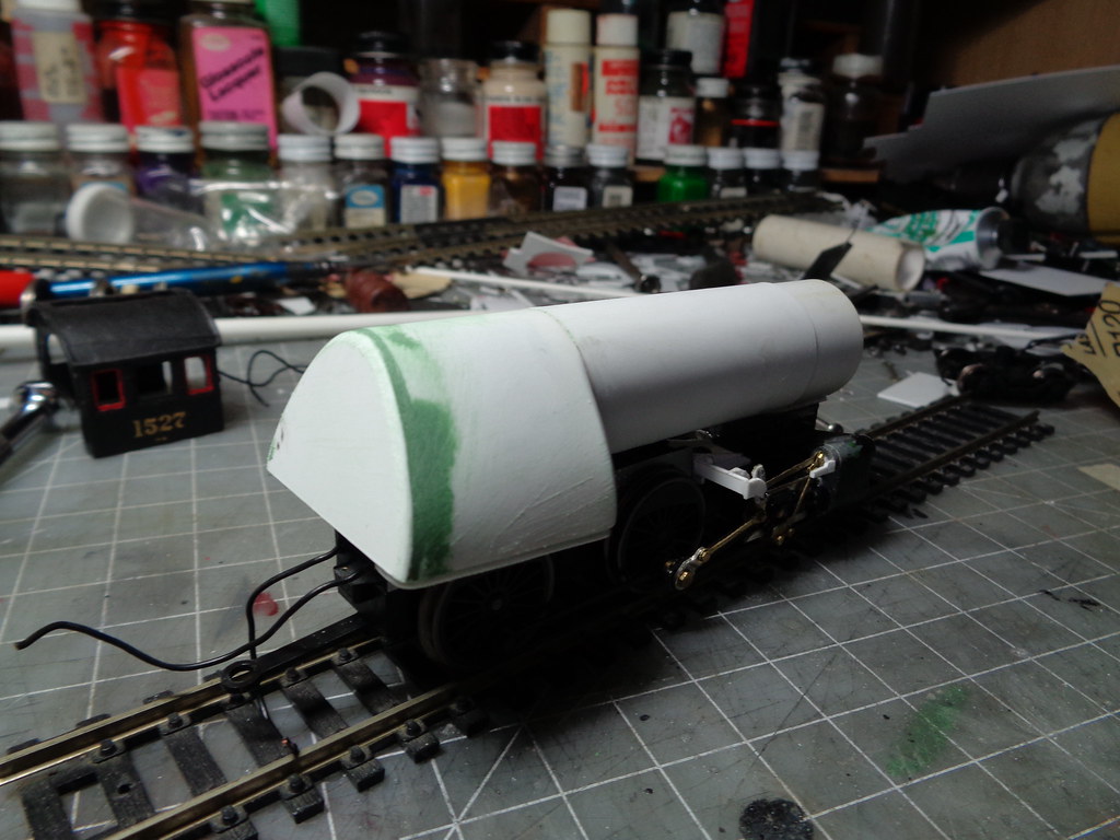
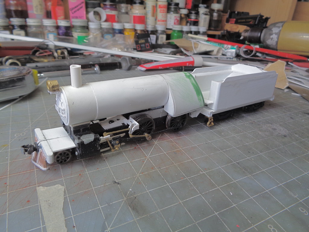
This is where it sits at the moment, ready for a firebox, though I think the boiler needs to be raised a little first.
The administrator has disabled public write access.

Modern D-8 Camelback Build 8 years 4 months ago #5006

  • HHS
  • HHS's Avatar
  • OFFLINE
  • Fireman
  • Posts: 54
  • Thank you received: 40
Casey,
One of my favorite engines. Look forward to seeing your work.

And for reference, or in case your like me skill wise, there is this from Overland.

Regards,
Hugh Sinn

IMAG0213800x478.jpg
The administrator has disabled public write access.
The following user(s) said Thank You: rdg1187prr

Modern D-8 Camelback Build 8 years 4 months ago #5023

  • MrBill
  • MrBill's Avatar
  • OFFLINE
  • Conductor
  • Posts: 169
  • Thank you received: 31
Your tenacity knows no bounds Casey. That valve gear build is very impressive. As you mentioned the lower driver classes are much more achievable given the availability of practical running gear. From what I have seen I think the only challenge you might have left would be building a bicycle arrangement.
Last Edit: 8 years 4 months ago by MrBill.
The administrator has disabled public write access.

Modern D-8 Camelback Build 8 years 4 months ago #5024

  • Casey
  • Casey's Avatar
  • OFFLINE
  • Conductor
  • Posts: 209
  • Thank you received: 57
Are you talking about the experimental holman speed truck?


I like odd ball, though not sure I would go that far haha.
The administrator has disabled public write access.

Modern D-8 Camelback Build 8 years 4 months ago #5025

  • Casey
  • Casey's Avatar
  • OFFLINE
  • Conductor
  • Posts: 209
  • Thank you received: 57
Work continued with putting a firebox on the boiler tube, starting with the frame.


Then the .010 sheet went on making the firebox, as well as the jacketing layer. Then the corners got sanded round.


The rear mounting was set using some screws that would otherwise be discarded. A rear plate is glue to the bottom to the firebox lined up vertically (meaning don't follow the back head line) while some square stock is glued to the frame built up enough to reach the rear plate. Then holes are drilled for the screws.


Wanting to get the tedious stuff I don't really look forward to out of the way my focus turned to the pilot. First the beam was set with the coupler pocket, making sure the coupler height was good. With the frame bent downward I cheated a little using an under shank coupler to get the right height without having to set the beam too high on the steam chest.


The height check...


Now the part I wasn't particularly looking forward to. Footboards are easy, just some plastic strips, tube pilots are a lot of precision starting with drilling. I drilled 7 holes on each side of the coupler pocket for .020 wire. 7 because that is what the proto type has.


Then wire was placed, shaped like a L and super glued in. The were made long and will be trimmed at a later step.


After set I tweak the rods in to place bending them trying to keep them symmetrical.


With space for the extra to hang down I put the engine on track to figure out where it all was going to be trimmed. This is where 2 .010 strips were then placed glued to a point at the center. I have tools to hold the sides in to curl around and glue in place.


After set the rods were sniped close to the plastic edges set then with a dremel I ground down the remaining to be flush with the bottom edge of the plastic.
The center 5 rods have their own little frame not directly attached to the bottom of the coupler pocket. Starting with .010 strips for the side then a strip with 5 holes drilled is centered in the side strips.


The rest is the same process as before just smaller pieces.


To make her a bit more presentable I thought is was time for a face. Starting with a base layer of .040 cut large and sanded down to the edge of the boiler. Then layering .040, .010 and .040 made the bulge and the door layers. The hinges, latches and number board are .010 styrene. For a headlight bracket I normally use a generic bowser one, but didn't have any. I didn't feel like ordering 1 part (having pretty much everything else I need to finish the project already) so I made one out of .010 and put the Reading style grab iron at the bottom. Also the stack will be trimmed down a little I just wanted to put something there and got the base piece in place.

[imghttps://c1.staticflickr.com/1/725/23775830281_12bb84dd2b_b.jpg[/img]


The tender started like a real one with making a frame. Made from .040 except the rectangle rod for the end beams.


I cut the old clips off the bachmann trucks and drilled for the screws I am using.


Here is the frame fitted with the trucks. The shell friction fit frame was placed, also some tender steps I happened to have.


Using dimensions from a previously built camelback, the shell went together rather quickly. Extra glue was added to the side seam to be sanded later as a filler.


With the basic structure in set the corners got sanded to a round edge.


This is where the project sits now, next will be getting the running boards and cab in.
The administrator has disabled public write access.

Modern D-8 Camelback Build 8 years 4 months ago #5026

  • MrBill
  • MrBill's Avatar
  • OFFLINE
  • Conductor
  • Posts: 169
  • Thank you received: 31
That Holman thing is wild. I was thinking one of the single driver jobs...
The administrator has disabled public write access.
Time to create page: 0.119 seconds

Today's Image

Did You Know?

September 6, 1945
#2100, the first T-1 4-8-4 steam locomotive, is outshopped at Reading.

Downloads

Operations Information

Click Here!A variety of Reading Company operations related documents, etc. that may be of use in your modeling efforts.

Operations Paperwork

Click Here!A variety of Reading Company operations paperwork, such as train orders, clearance forms, etc. that will help you operate your Reading layout in a prototypical manner.

Timetables, Rulebooks, Etc.

Click Here!Public Timetables, Employe Timetables, and Rulebooks that provide much useful operational information.

Modeling Goodies

Click Here!Signs, billboards, and other FREE goodies for your use.  We ask only that you help spread the word about The Reading Modeler!

Rolling Stock Reference

Click Here!Downloadable reference documents on the various classes of Reading Company Freight and Passenger rolling stock.

Thanks for Your Support!

If you find the content on The Reading Modeler valuable, won't you please consider supporting our efforts? Your donation will help to offset operating costs and acquire new material to share on the site. Thank you!

Amount: 

Advertisements