FacebookTwitterDiggGoogle BookmarksRedditLinkedinRSS Feed
Welcome, Guest
Username: Password: Remember me
This section of The Interchange provides a space where members of the Reading Modeler community can showcase their Reading modeling efforts. If you've got a project that you'd like to share, start a new topic and "show and tell" the group how you did it!

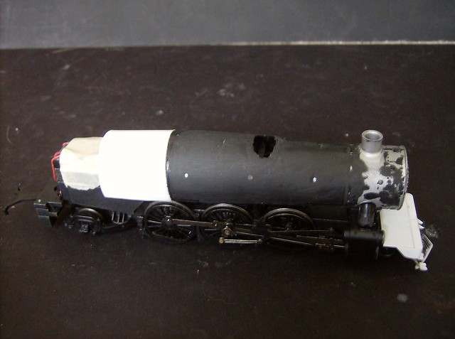
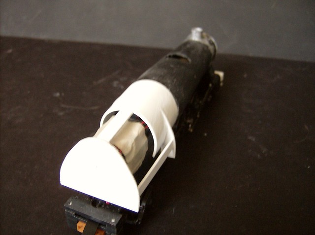
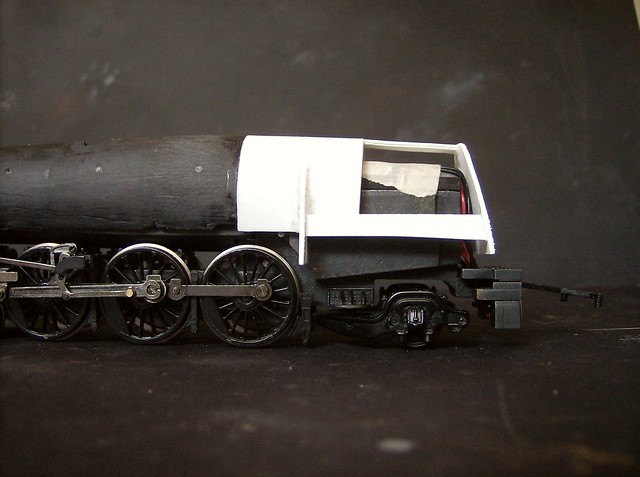
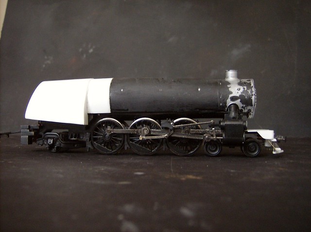
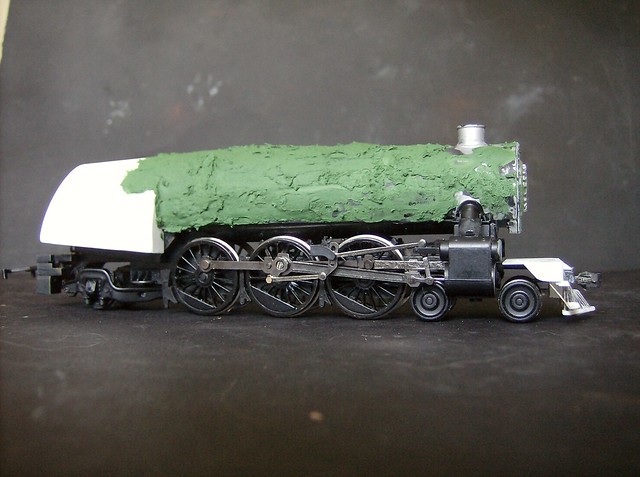
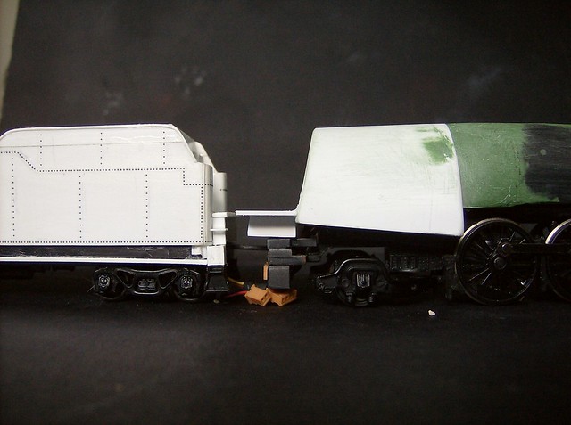
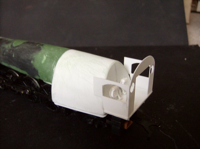
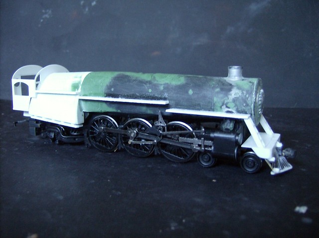
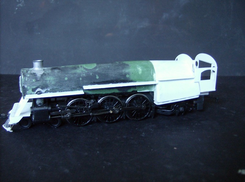
TOPIC: Semi-streamlined G-2sa

Semi-streamlined G-2sa 10 years 7 months ago #1896

  • Casey
  • Casey's Avatar
  • OFFLINE
  • Conductor
  • Posts: 209
  • Thank you received: 57
The K-4s firebox angles from the bottom way up to the top of the boiler where the belpaire square from ends, a Reading wootten is not so elongated so there will be a spacer before the actual firebox begins. The piece is made from a section of .040 of no real exact proportions, it need to go at least past the last break shoe and not further then the frame casting, with the bottom being inline with the exsisting boiler section. I flexed it around my finger to shape it, if you try to bend it too sharply it will just snap. Then glue it to the back of the existing boiler section, if it does not line up perfectly its ok there will be lots of puttying.


Next to go in place is the front hip joints of the firebox made of more .040 being sapped in a curve to a point at the top its about 1" high by 5/16" wide at the bottom. The inside gets shaped to fit the boiler extension piece, they get aligned with the middle of the last break shoe. Sorry its not more exact a lot of it is tweaking and sanding once the piece is on, the pictures represent a base state, it went through a lot of tweaking before the firebox frame got wrapped. A way to check progress is set it on a flat surface and use the steam pipes on the smoke box as a "level" base if the firebox front joints aren't level with them the shell will rock back and forth. The next piece to get ready is the backhead symmetrically shaped in the flat sided arch the bottom is about 1 1/2" the hight of the center of the arch is about 1 1/16". The backhead should almost rest on the back of the frame casting at about a 10 degree angle tied in with spacer bars made from .040, should also rest about 1/8" above the frame illustrated in the third picture below. The boiler its self in a finished state will be kind of a big arch itself which naturally happens with the angled cut I mentioned in the last post.


Next is to actually wrap the firebox frame just created. This is done with .010 for its flexability I do it with an oversized piece with the only flush sides being on the sides with the hip joints at the front of the firebox, once glued in place take an exacto and trim the access from the backhead to be flush and connect the dot from point A to B for the angle of the bottom of the firebox. once trimmed sand the front and back corners to be rounded edges. Now there will be a bump from the extension piece to the actual firebox, that will be taken care of with the puttying.


Once the frame is covered I added bottoms to the firebox to add some rigidity of the whole shape, it also works as a good place to glue the ash pans.


And then there was putty, let sit over night, may take more then one application.

The administrator has disabled public write access.

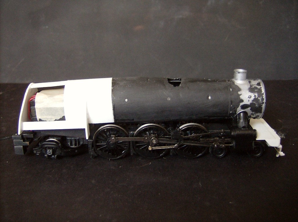
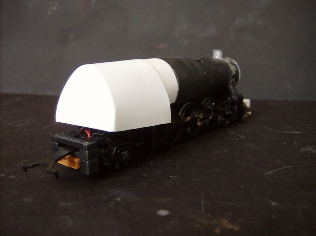
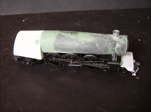
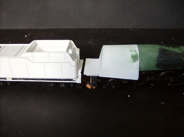
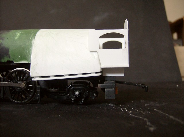
Semi-streamlined G-2sa 10 years 6 months ago #2048

  • Casey
  • Casey's Avatar
  • OFFLINE
  • Conductor
  • Posts: 209
  • Thank you received: 57
So tons of sanding and a pair of hulk hands later you get a smooth boiler. If filled area from the sand dome isn't naturally flush with the line of the boiler it does not matter too much, the new sand dome goes in basically the same spot.


Now the task is how do you anchor this boiler, or at least the back of it since the front is already taken care of from the original mold. I used the original screw and hole with a piece of styrene rod. The styrene rod has a hole drilled in the bottom and the screw worked in and out a few times to mold the teeth. The piece was made as long as needed to prop the back of the boiler to where I thought it looked right, basically eyeballed, I think about 1/4" long. Then mount the rod piece with the screw so it sits where it wants to then super glue the bottom of the firebox to the rod.


Next is the cab floor a piece of .040 9/16" x 1 13/32" centered glued to the back of the firebox at the height of the tender gangway floor. The side walls are cut to fit at the with of the metal frame with about 1/8" of the floor sticking off the back. (the pieces in the picture still needed a little more shaping) Also once the floor is in place I put a shim in between the mounting rod piece and the floor and glued it all together to make it more solid.


A view of the line up, I make the engine and tender as close as possible for realism, but it makes it so it runs on a minimum of 22" radius.


Now is a good time to do any cab interior or once you have the 2 cab side walls up. I decided not to do too much of a cab interior, I did one on the I-9 and that was basically $50 in parts I'll never see. So I did some styrene fire doors. I was experimenting a little and was going do a styrene interior and thought it would be better with the cab walls in place but there isn't much room to work in. I did a throttle later and then moved on.

The ash pans are in place now too made with .040 spacers about 1/8" wide evenly space glued to the firebox bottoms from the last post, then capped by a piece the same size as the firebox bottoms from .040 and I sanded the edges rounded from bottom to top.
The administrator has disabled public write access.

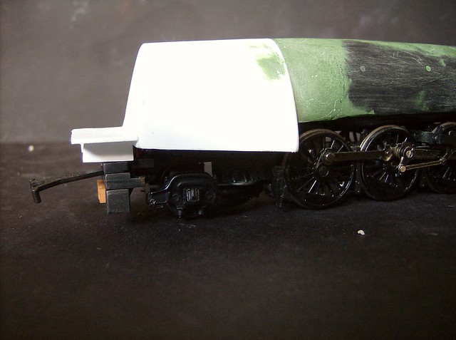
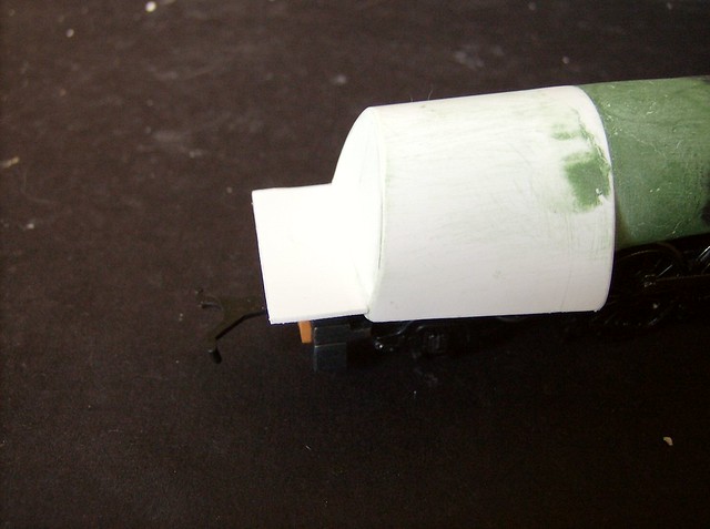
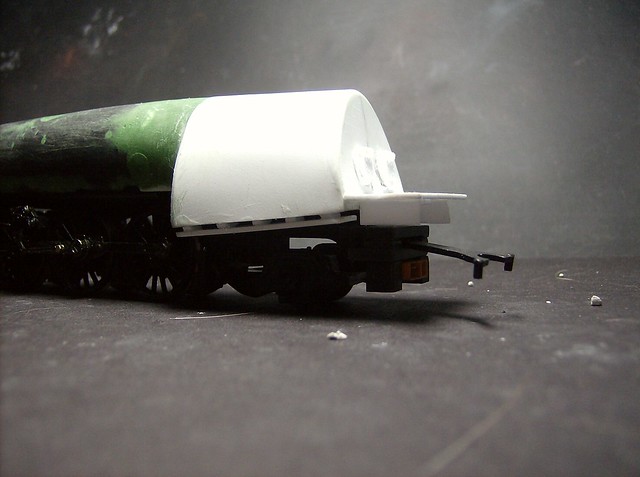
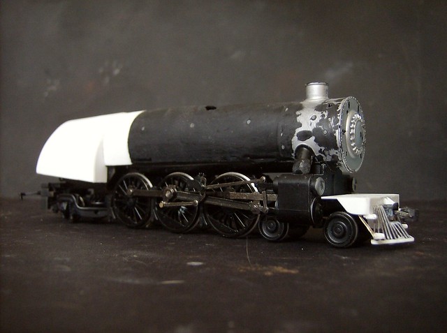
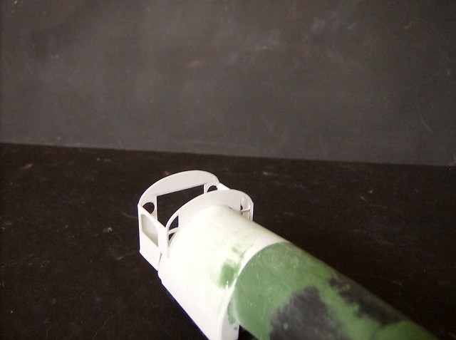
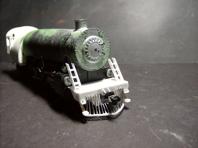
Semi-streamlined G-2sa 10 years 6 months ago #2069

  • Casey
  • Casey's Avatar
  • OFFLINE
  • Conductor
  • Posts: 209
  • Thank you received: 57
The cab Starts with the 2 sides and the back pieces.

The sides are the same measurements in .010 7/8" wide by 3/4" high.

The notch for the firebox is (from the front) 5/16" up and 5/32" in, the bottom of the cab is 9/16" wide from the back the angle is connect point A to point B.

The Window is 11/32 from the bottom, 1/16" from the back and 7/32" from the front. The top of the arch is 1/16" from the top.


The back piece is 1 1/8" by 1 13/32"

The centered inside is 13/16" x 13/16"

Where the curve starts is 3/4" up.


They are then glued in place, these are the measurement I came up with after the fact, the way I did it was make the 2 sides based on I-10 measurements, then shape the back to fit. Then glued the 3 pieces in place giving the floor of the cab a little space out to make the walking ledge then shape the front piece to first cleanly sit on the firebox once it sits right mark where the top of the side walls sit, then hold it up to the in place back and trace the roof curve so they are the same. Then I cut the roof line and the windows out of the front.


Once all this was done I added little filler shims to the 2 sides of the openings on the front of the cab resting on the firebox to close it up. 2 small rectangles and 2 small triangles shaped to fit.

Now that the base of the cab is in place the other visual marker needed to do the running boards is the front step ladders.

They are 2 pieces of .010 about 3/4" x 1/8" with the angle they lean eyeballed with other steam locomotives. The 2 sides are spaces about 5/32" apart with the outside one being glued right to the edge to the pilot. Then 3 steps are fitted equally spaces.


In the past I have used left over ladders from spectrum 2-8-0s that didn't need them anymore.

Then the running boards were fitted made from .040. These were really just eyeballed with visual queues being the rear one is flush from the cab to almost flush with the firebox front. The front is flush from the ladders to about 3/4 of the first driver. The middle piece is filled in between none of them should exceed the width of the cab. Also you will need to make a notch in the front section for the steam pipe that comes out of the smoke box.

Make sure the shell is sitting in the final position it helps to eye things level.


Last Edit: 10 years 6 months ago by Casey. Reason: fix a picture link
The administrator has disabled public write access.
Time to create page: 0.111 seconds

Today's Image

Did You Know?

July, 1947
The new Lebanon Valley Branch bridge over the Schuylkill River at Reading, PA is completed, featuring the large "READING LINES" letting.

Downloads

Operations Information

Click Here!A variety of Reading Company operations related documents, etc. that may be of use in your modeling efforts.

Operations Paperwork

Click Here!A variety of Reading Company operations paperwork, such as train orders, clearance forms, etc. that will help you operate your Reading layout in a prototypical manner.

Timetables, Rulebooks, Etc.

Click Here!Public Timetables, Employe Timetables, and Rulebooks that provide much useful operational information.

Modeling Goodies

Click Here!Signs, billboards, and other FREE goodies for your use.  We ask only that you help spread the word about The Reading Modeler!

Rolling Stock Reference

Click Here!Downloadable reference documents on the various classes of Reading Company Freight and Passenger rolling stock.

Thanks for Your Support!

If you find the content on The Reading Modeler valuable, won't you please consider supporting our efforts? Your donation will help to offset operating costs and acquire new material to share on the site. Thank you!

Amount: 

Advertisements