
Modeling a Reading GHm Plate-Steel Gondola in HO Scale
|
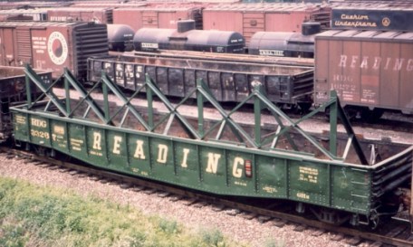
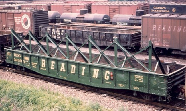
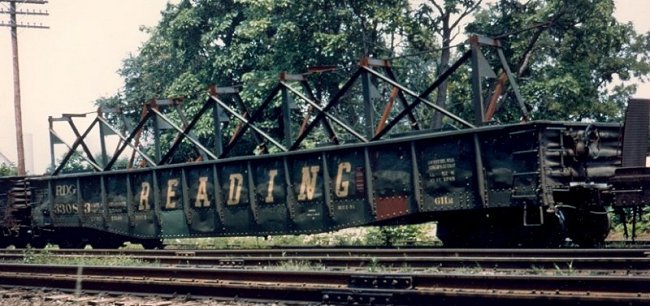
The Reading wasn't just about coal, especially in its later years. The railroad also played a significant role in servicing the Pennsylvania steel industry, at locations like Bethlehem, Steelton, Coatesville, and Fairless. In the 1960s, the Reading modified several 54' GHm-class gondolas to carry plate steel. Known numbers (courtesy of John Hall) are 33051, 33083, 33106, 33194, 33267, 33333, 33553, 33575 and 33992. The prototype photo at left shows that the Reading basically did a "prototype kitbash," adding the vertical bracing while maintaining the integrity of the original carbody. |
 |
|
|
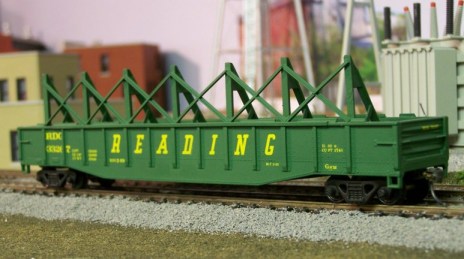
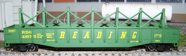
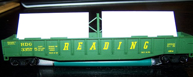
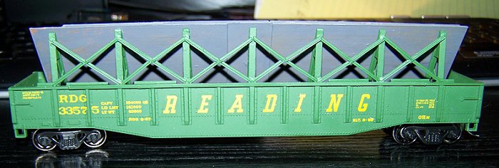
At right is a photo of the author's model of Reading #33267, inspired by the prototype photo. This article will show you how to build a similar car for your layout. Please take note: The original model was using the above photo as a guide, rather than following a prototype blueprint. This article is not an attempt to strictly replicate the prototype; it is rather an effort to create a reasonably credible replica using readily attainable materials and simple construction methods. For those wishing to take the project to a more detailed level, the prototype photos included in the article should be useful. An undecorated Con-Cor 54' gondola was used as a starting point for this project; however, any undecorated gondola of appropriate length and sill configuration should work. Refer to the Bill of Materials below for additional supplies needed, gather your tools and let's begin! |
Bill of Materials 54' undecorated gondola (modeler's choice, as long as length and sill configuration are appropriate) Kadee #5 couplers Plastruct: 90563 3/32" - 2.4mm Styrene Tee Plastruct: 90501 3/64" - 1.2mm Styrene Angle Evergreen: 8208 2x8 Styrene Strip Evergreen: 9015 0.015" Sheet Styrene - NOTE: You do not need much of this, just enough to cut a piece 3' wide by 14' long Evergreen: 9020 0.020" Sheet Styrene - NOTE: This is for making the plate steel load, one sheet will be sufficient. Brake Wheel (modeler's choice if your car does not come with one) Paint: Reading Green (modeler's choice, project car was done using Floquil) Decals: The original project car was lettered using Herald King set B-501, cobbling bits and pieces of several sets together to get the proper dimensional data. However, The Reading Modeler has developed an HO scale decal set for Reading gondolas in the green and yellow "speed lettering" scheme that will accurately letter these cars and other green Reading gons with no need to piece multiple sets together. These decals are available from the Reading Modeler Company Store.[--pagebreak--]
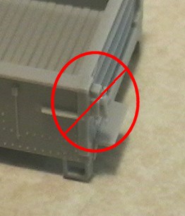
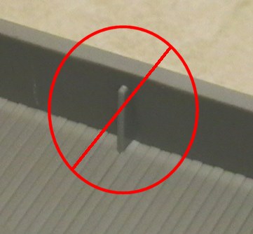
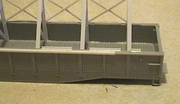
| Step 1. With a fresh chisel blade, and if your car has them, remove the cast on brake detail and the bracing in the center of the car, as highlighted in the photos at left. You can now set the car aside, as we're going to turn our attention to fabricating the vertical bracing.
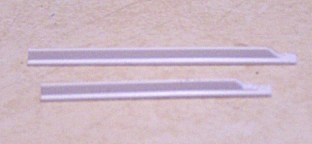
The next few steps are to construct the brace assemblies, of which seven are needed to complete the car. Step 2. Cut seven 9'6" pieces and seven 12' pieces of Plastruct Tee. The shorter piece will form the upright, while the longer piece will form the diagonal brace. |
|
|
Step 3. With a sharp #11 blade, cut about 1'6" of the cross piece away from one end of all of the pieces you just cut, so that they look like the photo at left. The pieces will be mated at this end on an angle, so you need to cut this material away so they fit together properly. Step 4. Now let's make the triangular reinforcement plates. Cut seven rectangles of Evergreen 0.015" sheet styrene 2' wide and 3' long. After you've cut these pieces, cut them in half diagonally so that you end up with 14 "right triangles" with a 2' base and a 3' height - remember high school geometry? A Northwest Shortline "Dupli-Cutter" is handy for the repetitive cuts.
|
|
[--pagebreak--]
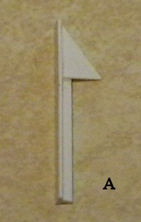
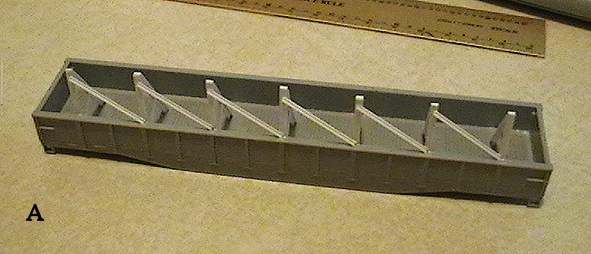
Step 5. After you've cut the triangular pieces, you are ready to assemble the first brace. The row of photos below shows the step-by-step process. You will need 7 brace assemblies - I recommend constructing one "perfect" brace all the way through to completion, and using that as a template for the remainder.
A. Starting with one of the 9'6" uprights with the cutaway portion from Step 3 oriented toward the top, cement one of the reinforcement plates to the upright along the 3' leg of the triangle, with the top of the triangle even with the top of the upright. Use your X-Acto knife to push the plate snug against the "tee" part of the upright.
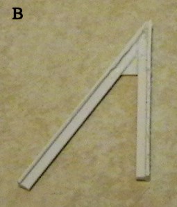
B. Next, cement the diagonal brace to the "open" hypotenuse (another geometry term) edge of the triangle, so that the cutaway portions of both legs of the brace meet at the top. You may have to cut away more of the cross piece of the "tee" to get a proper fit. Again, make sure that the reinforcement plate is snug against the "tee" part of the diagonal.
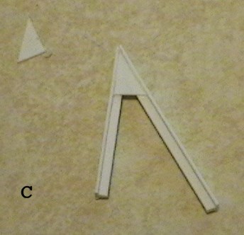
C. Cement a second reinforcement plate to the opposite side of the brace, pushing it snug against the "tee."
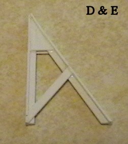
D. You will note that diagonal leg of the brace is longer than the upright. This was intentional to allow some leeway for trimming. Carefully trim the end of the diagonal brace so that it is even with the upright. This will allow the brace to sit flush against the carbody floor.
E. With the piece oriented as shown, find the midpoint of the diagonal brace. Cut a piece of the Evergreen 2x8 strip to fit between the bottom of the upright and the midpoint of the diagonal brace and cement in place. You will need to trim it up a bit to get the proper angles for a snug fit. If you want to really go for an accurate model, you can substitute pieces of the Plastruct angle in this step, since the prototype actually used angled steel as reinforcement.
|
|
|
|
|
|
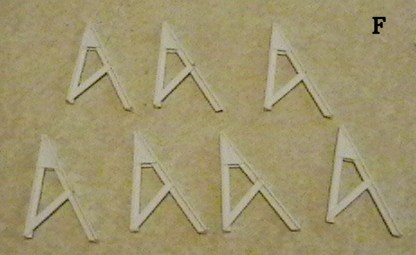 |
F. Repeat the above steps until you have completed seven braces. They should all be consistent in size, angles, etc. so that when they all have a consistent height and appearance when installed. This will also help the removable plate steel load (which we'll construct later) rest properly against the diagonal brace when the car is "loaded". Now would also be a good time to do any needed cleanup on the completed braces, sanding, filing, etc. until you are satisfied that you have seven identical pieces. |
[--pagebreak--]
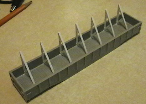
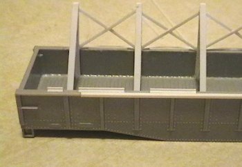
Step 6. Using the below photos as a guide, cement the braces to the inside of the carbody, making sure both "feet" of the brace touch the car floor, and that they are perpendicular to the car side. If you look down the length of the car, the diagonals should all be at the same angle, and the angled reinforcement pieces should all line up. The prototype upon which our model was based (#33267) had the bracing installed with the "B" end to the left, but the prototype photos elsewhere in this article showthe braces installed on either side of the car, so it's your choice based on which car you're representing.
[--pagebreak--]
|
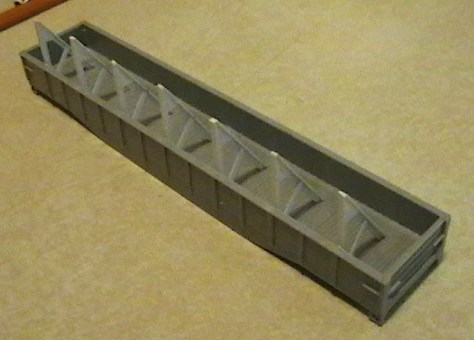
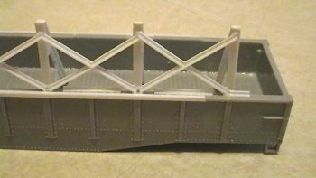
Step 7a. Now we'll build the angled bracing that reinforces the brace uprights. Start by cutting 6 pieces of the Plastruct 90501 angle 8'9" in length. As shown in the photo below, cement these pieces diagonally between the uprights, positioning the ends of the angle in the center of the uprights to allow space to anchor the opposing pieces in the next step. If mounted in this fashion, there should be a bit of space between the top of the angle and the top of the upright. |
 |
| Step 7b. To complete the angled bracing, the "opposite" diagonal is constructed in two pieces, one each above and below the diagonal that was installed in Step 7a. Cut 6 pieces of Plastruct angle 4' in length, and install between the top chord and the underside of the full length diagonals as shown in the photo at right. The end that mates with the full-length diagonal should be trimmed on an angle to give a smooth tight fit, and the end that rests against the top chord should be trimmed on an angle so that it appears vertical, and should match up with the lower ends of the full-length diagonals as shown. | 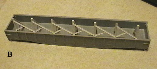 |
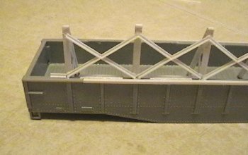
| Step 7c. For the angled bracing above the full-length diagonal, cut 6 pieces of Plastruct angle approximately 5' in length. These will be oversized, but we will trim them down for a snug fit. Cut a slight angle on the "bottom" end of the piece that will fit against the full-length diagonal, and trim the "top" end to the proper length to fit as shown in the photo at left. When you cement them in place, it should look like the diagonal that goes from bottom left to top right is one solid piece. The photo at left shows what the car should look like after all bracing has been installed. | 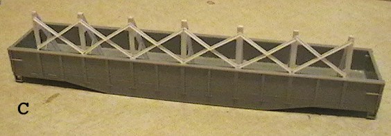 |
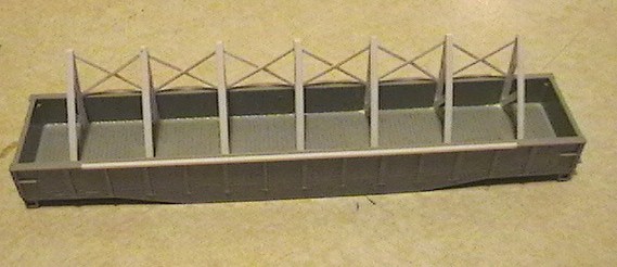 |
Step 8. Cut two pieces of Plastruct 90501 angle 40' in length and install one piece on each side of the car. as a reinforcement brace along the top chord as shown in the photo at left. The angle should sit over the top and side of the car - refer to the prototype photo at the beginning of the article. We're almost finished! |
[--pagebreak--]Step 9. In order to prevent the loaded plate steel from shifting during transit, the Reading installed metal rods across the carbody to act as a stop. In addition to drilling holes in the car sides to secure these rods, additional pieces of angle iron with several holes to facilitate securing varying lengths of plate were installed along the top chord. To model this, cut 4 pieces of Plastruct 90501 angle 18" in length, and 8 pieces that are 4'6" in length. Cement along the top chord as shown in the 4 photos below.
|
|
|
|
|
|
Congratulations! You have completed the major construction on your GHm Plate-Steel gondola! As a last step, add any desired superdetail parts, such as additional grab irons, steps, etc., attach the brake wheel of your choice to the "B" end of the car, and we're ready to roll it into the paint shop!
[--pagebreak--] Painting. Before getting ready to paint, do any needed trimming, filling and sanding until you are satisfied with the overall appearance of the car. Wash it gently with warm soapy water and allow to dry. Paint the car Reading Green using whatever method you prefer - painting methods are beyond the scope of this article. The prototype photos we have seen all show these cars painted green; we have not seen any painted black.
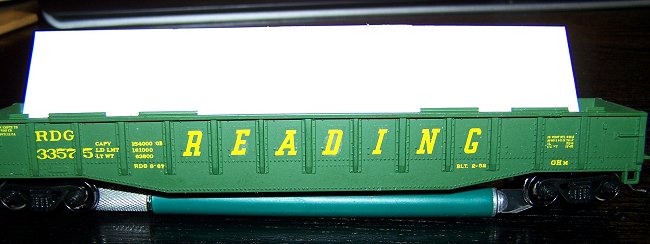
Lettering. The gondola can be lettered using the Reading Modeler Yellow Gondola Decal Set. These cars were all 52'6" cars from class GHm, and the exact car numbers that were modified in this fashion are listed at the beginning of this article. Here is a photo of the project car after painting and lettering.
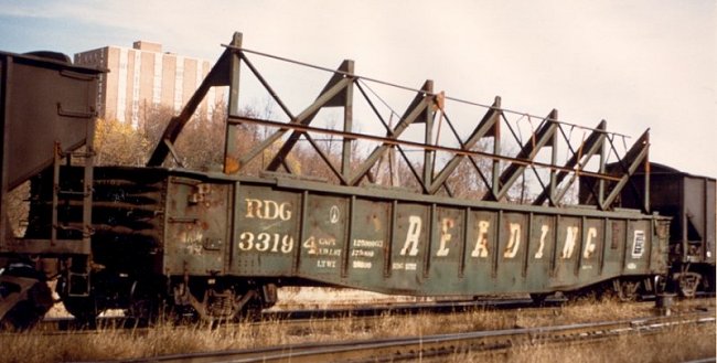
The following photos provide a general guide for lettering your car. They also show some of the later modifications that were done to these cars, including changing the angle of the main braces (presumably to accomodate larger pieces of plate steel) and adding additional bracing in various locations. It would be a fairly straightforward matter to model one of these alternative approaches using the same styrene stock as outlined in the instructions, eyeballing the measurements to approximate the photos.
|
|
|
|
|
|
[--pagebreak--]
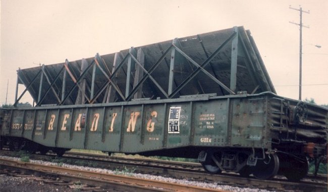
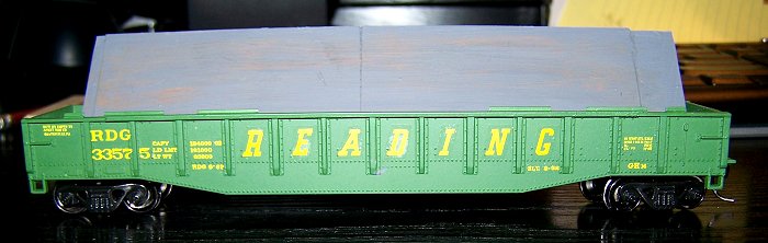
| After painting and lettering the car, the last step is to construct a removable plate steel load for the car to simulate empty/loaded operations. As can be seen in the photo of #33575 below, plates of varying lengths were carried by these cars, stacked against the diagonal bracing and staggered depending on the length of the plates. Ties were also used to provide additional bracing. Also, close scrutiny of the photo will show the holes drilled in the angles along the top chord for the rods to be used as stops, as can be seen at the right end of the car.Cut 3 or 4 strips 1 5/8" wide and 6" long from a sheet of Evergreen 0.020" styrene, then cut those strips in half so that you have pieces of sheet styrene that are 1 5/8" wide and 3" long. | 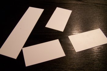 |
To build the load, start by laying two pieces of styrene against the diagonal bracing of the car. Leave the center diagonal brace exposed, and leave some space between the styrene and the car ends, as seen in the first photo below. Cement a third piece of sheet stryene over the first two, covering the gap in the center as seen in the second photo below. This will simulate plates stacked on top of each other, and will also help the load sit more securely in the car. Add two or three more plates on to the load, staggering them in a similar manner.
[--pagebreak--]After allowing the assembly to dry, paint and weather the load to your liking, using the photo of the loaded car on the previous page as a guide. Here are photos of our completed car with a painted load.
This completes the "basic" construction of the car and load. If desired, you can add additional details to more accurately represent the prototype. Although we have no photographic evidence, these cars likely had blocking installed on the car floor to help hold the steel plates against the diagnonal bracing and to mitigate shifting during transit. This could be simulated with stripwood ties cemented to the floor. Also, our photo of the car under load shows ties placed between the uprights for additional support of the load - if you're going to make the load permanent, this could be modeled with stripwood. The steel plates in the photo also appear to have strapping on them to keep them together. Extremely thin sheet styrene, or perhaps even dental floss (the flat kind) could be used for this detail. Finally, threaded steel rods were installed through the car sides and through the angle iron along the top chord as stops to prevent the load from shifting; simply drill appropriately sized holes and slide pieces of wire through them to replicate this feature. If desired, you could finish off the outside ends of these rods with a nut-bolt-washer casting. Our intent with this article was to demonstrate how to build the basic carbody - the detailing is up to you.
We hope you've enjoyed this article - building one of these unique cars will help you model the steel trade on the Reading, which was an important part of operations in the railroad's later years!
Today's Image

Did You Know?
Downloads
 A variety of Reading Company operations related documents, etc. that may be of use in your modeling efforts.
A variety of Reading Company operations paperwork, such as train orders, clearance forms, etc. that will help you operate your Reading layout in a prototypical manner.
Public Timetables, Employe Timetables, and Rulebooks that provide much useful operational information.
Signs, billboards, and other FREE goodies for your use. We ask only that you help spread the word about The Reading Modeler!
Downloadable reference documents on the various classes of Reading Company Freight and Passenger rolling stock.