FacebookTwitterDiggGoogle BookmarksRedditLinkedinRSS Feed
Welcome, Guest
Username: Password: Remember me
This section of The Interchange provides a space where members of the Reading Modeler community can showcase their Reading modeling efforts. If you've got a project that you'd like to share, start a new topic and "show and tell" the group how you did it!

TOPIC: Reading I-6 Build

Reading I-6 Build 8 years 11 months ago #4432

  • dave1905
  • dave1905's Avatar
  • OFFLINE
  • Brakeman
  • Posts: 22
  • Thank you received: 2
Very interesting. I am thinking about how to do some I-1 thru I-4 conversions from the Roundhouse 2-8-0 (and 4-4-0).

How did you build the firebox grate area, are those just matching pieces glued to the sides of the boiler or is it a plate attached to the end of the boiler?
The administrator has disabled public write access.

Reading I-6 Build 8 years 11 months ago #4433

  • Casey
  • Casey's Avatar
  • OFFLINE
  • Conductor
  • Posts: 209
  • Thank you received: 57
It was done as 2 side pieces and a frame connecting the backhead. If you can make it to the Meet I will be going over this boiler construction in depth and then hopefully I have the footage from it posted too. But in the mean time here are pictures of a pre-wrapped firebox on the Lehigh Valley N-3. It's different shape but same concept.

The administrator has disabled public write access.

Reading I-6 Build 8 years 11 months ago #4435

  • dave1905
  • dave1905's Avatar
  • OFFLINE
  • Brakeman
  • Posts: 22
  • Thank you received: 2
Thanks for the feedback. I will need to try a couple of these engines. I am modeling the W&N branch in 1900-1905 so small camelbacks will be major part of my roster.
The administrator has disabled public write access.

Reading I-6 Build 8 years 11 months ago #4451

  • Casey
  • Casey's Avatar
  • OFFLINE
  • Conductor
  • Posts: 209
  • Thank you received: 57
I got a lot of this done this week, taking advantage of the cool weather. I had this feeling the boiler was too small and had to prove to myself that was I thought I was doing was right and pushed it until I got to that point and then decided to work on it more.

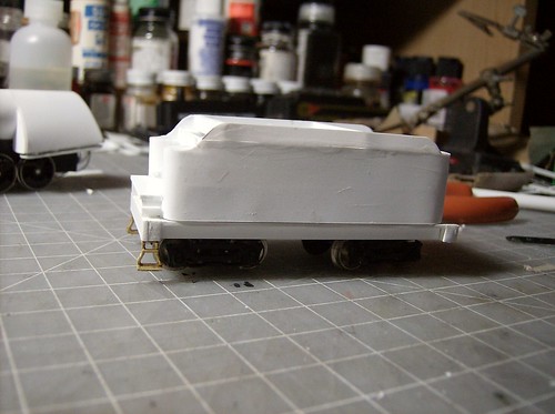
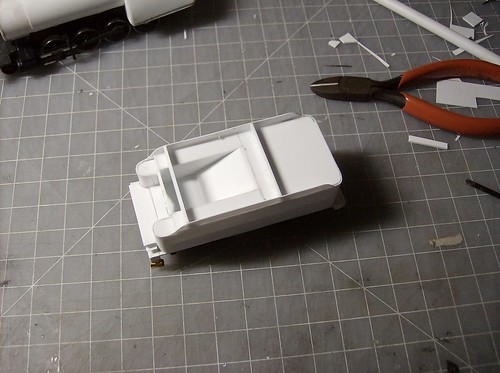
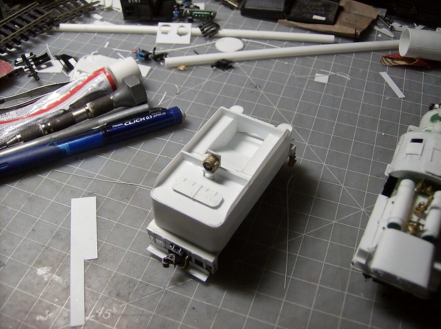
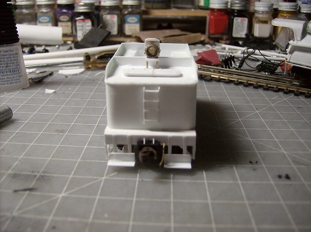
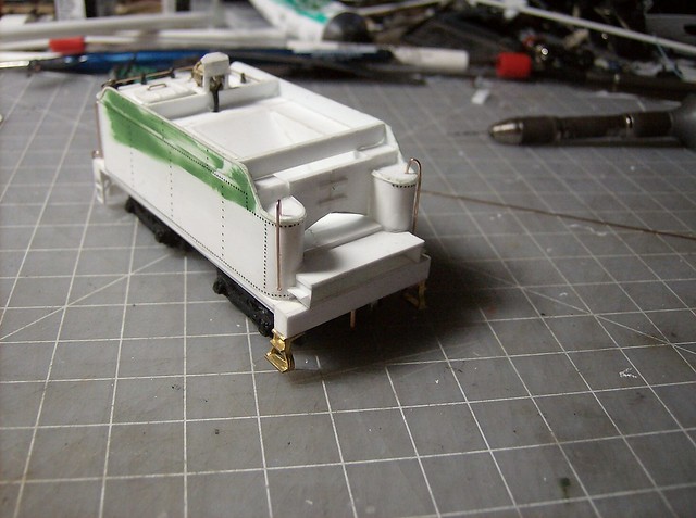
Work resumed on the tender making the coal bunker.


Then the sides when up being .010 and 1/8" high. The bunker walls followed.


Using the bottom of the firebox as a guide the deck was placed.


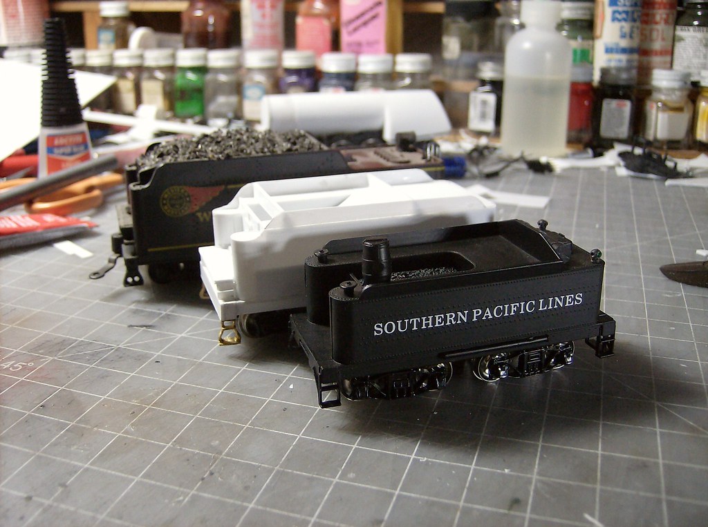
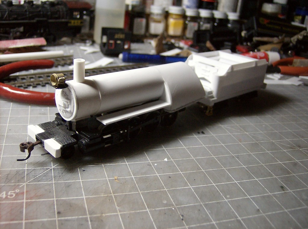
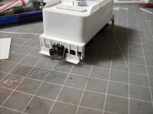
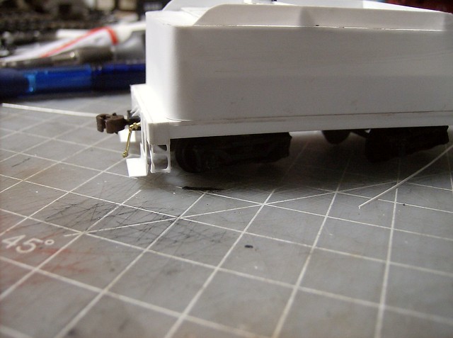
Here is a height comparison of the original to the built to an IHC more modern tender. As you can see I was going for in between.


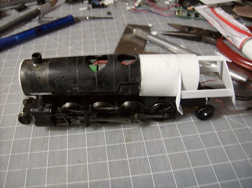
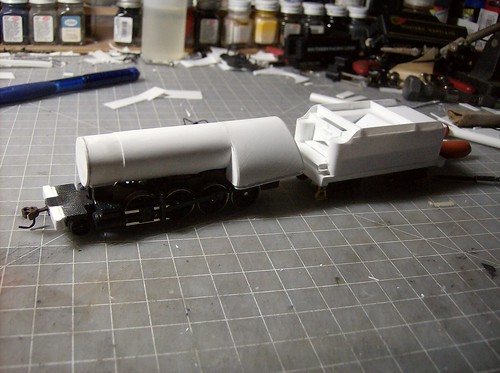
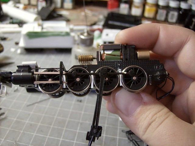
With a bulk of the tender done focus returned to the engine starting with placing the ash pans. They are made from .040 with .040 spacers.


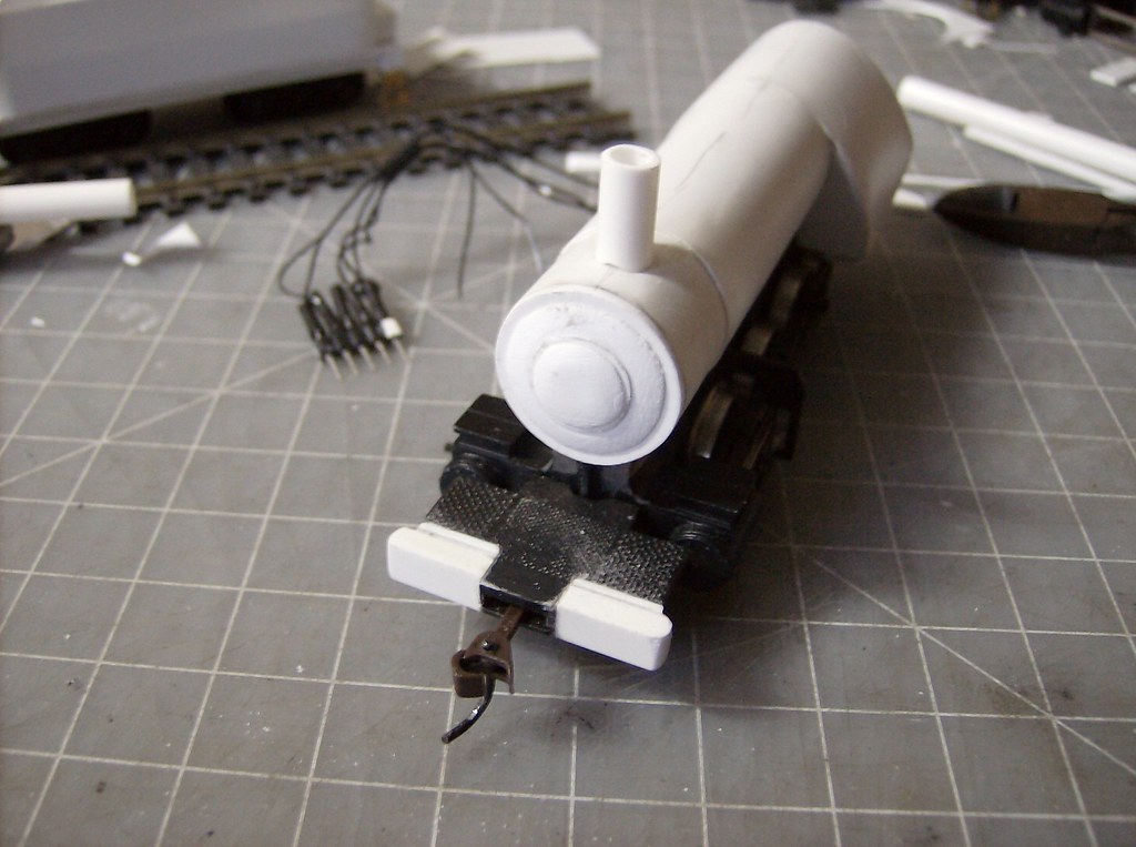
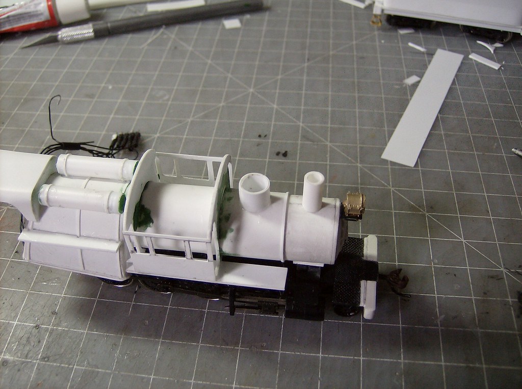
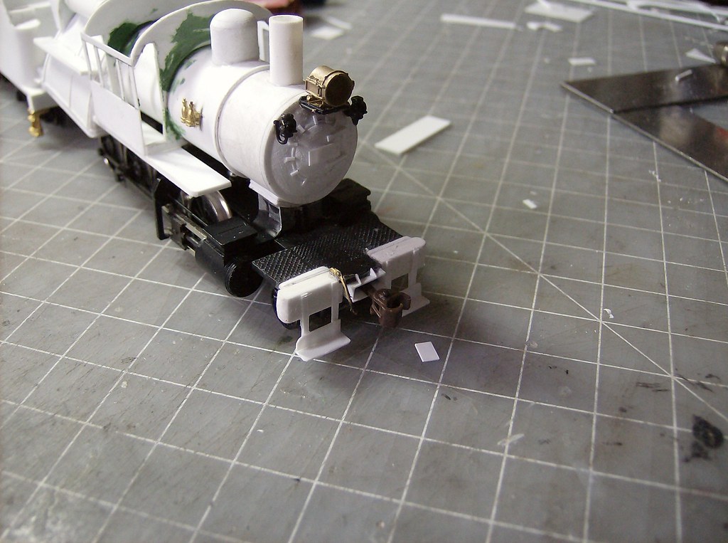
A piece of styrene was cut as a guesstimate which can always be sanded later. Then the smokebox base was placed in the .040, .010, .040 sandwich I have used before. The hinges and latches are .010 pieces, the headlight and number board were also place at this point. I chose the rectangular number board which the engines got late in life just before retirement. Through most of their career they would have had a circle number board.


Then the running boards were installed glued to the front of the firebox.


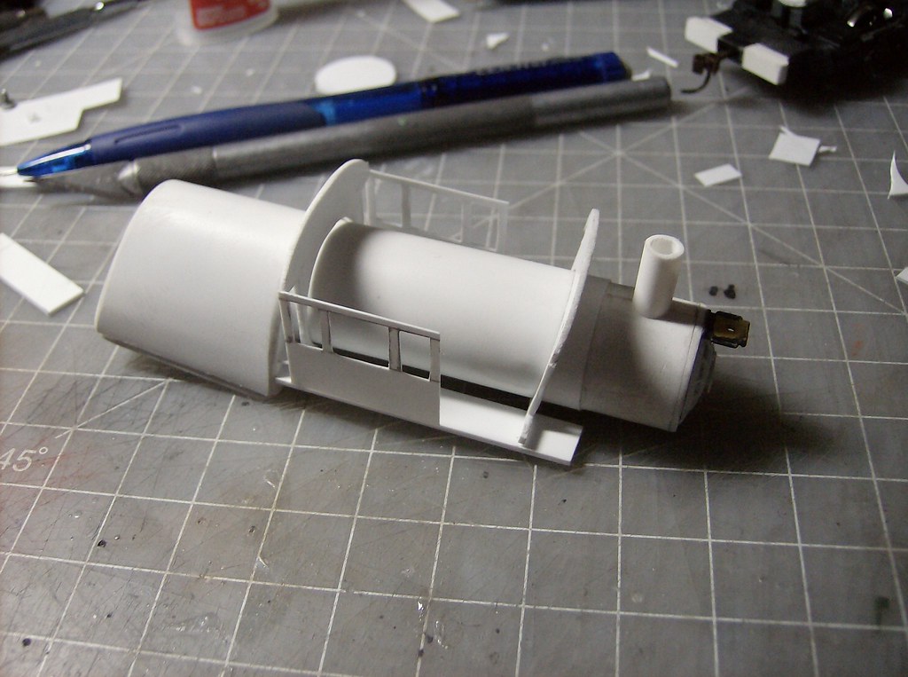
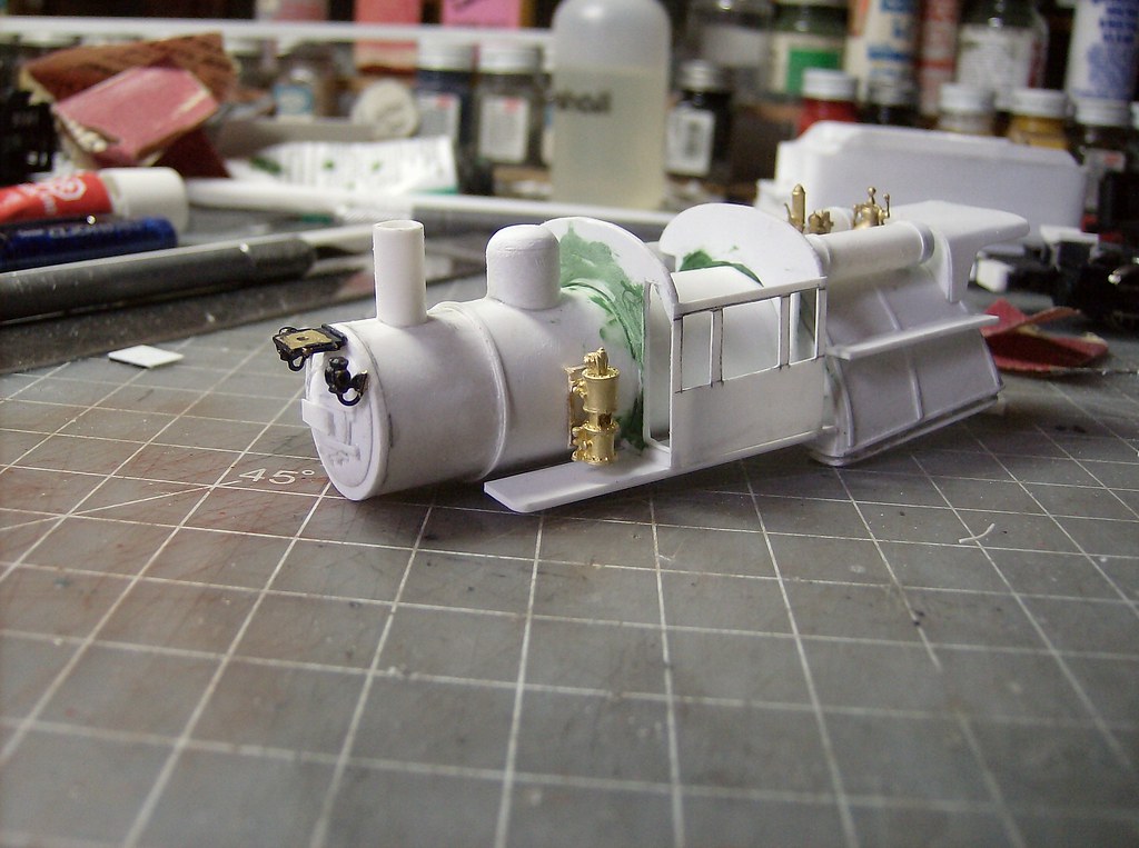
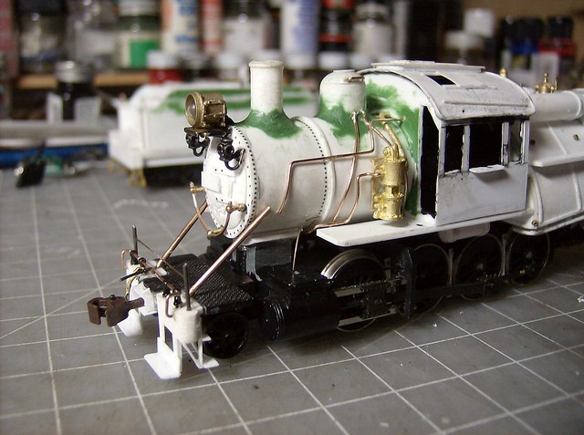
I wanted to revise my cab design a little as some of the full .010 cabs have drooped a little after being finished. This is normally fixable but I'd rather not have to. I went with .040 front and back walls with the rear section being glued to the running board first. Then the cab sides, still .010 were glued to the rear wall, and the front wall followed being glued to the side then the floor. This gut down on measuring and having to place the front and back perfectly before the sides went in. I also meant to do the window frames on the cab side before they were installed but forgot. Not a huge problem its just easier to do it that way. Putty was used later to fill any open seam around the boiler.


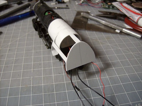
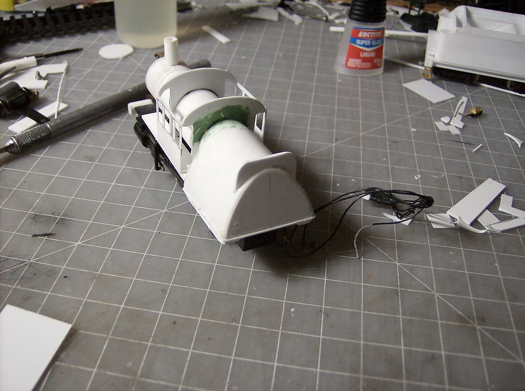
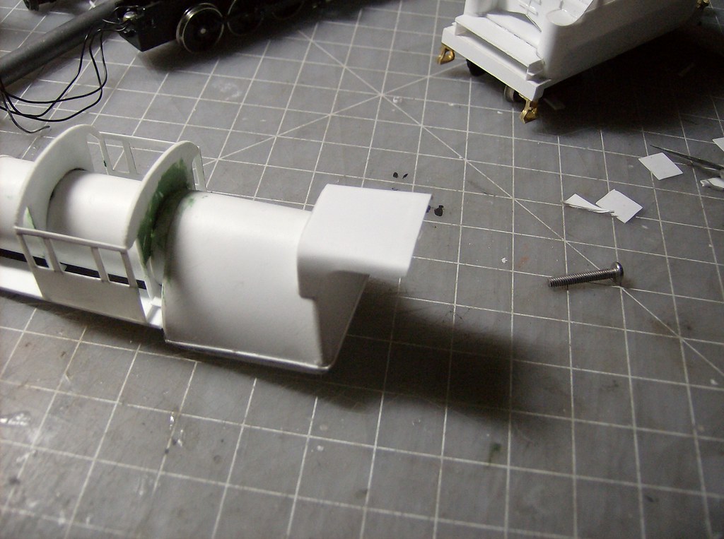
Next was the rear shade, starting with the .040 base. Then a piece of .010 was wrapped around the frame. To keep the shape at the end, a piece of .040 is glued to the rear under side.


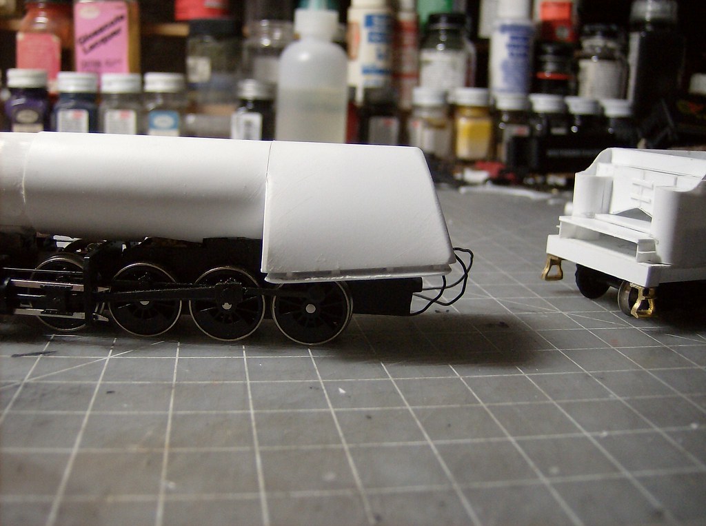
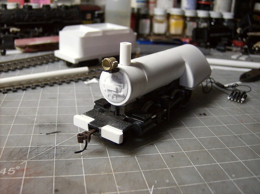
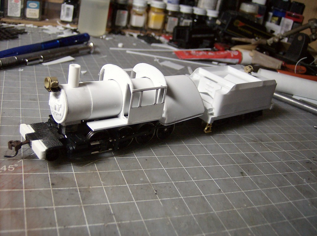
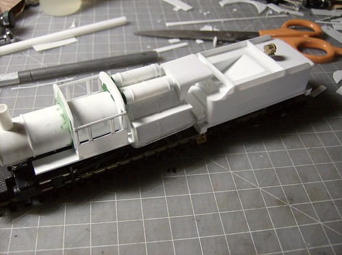
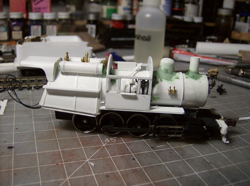
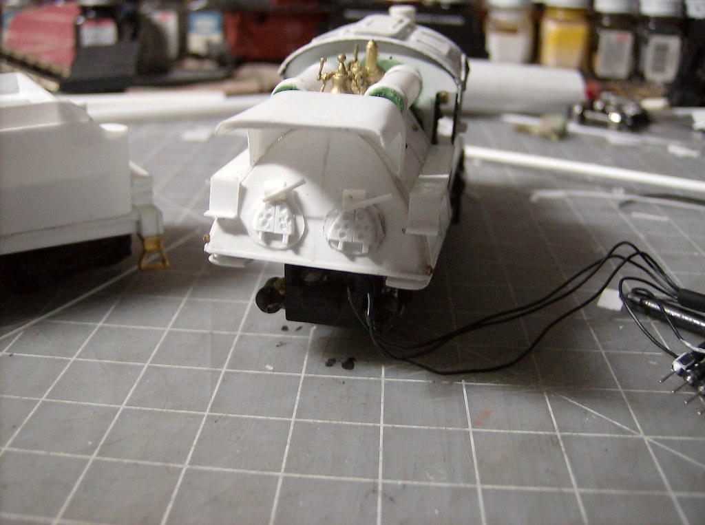
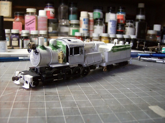
The boiler bands and air tanks were next to go on.


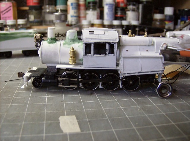
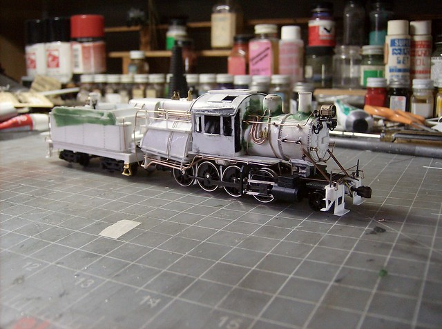
This was the point it was looking right to me.


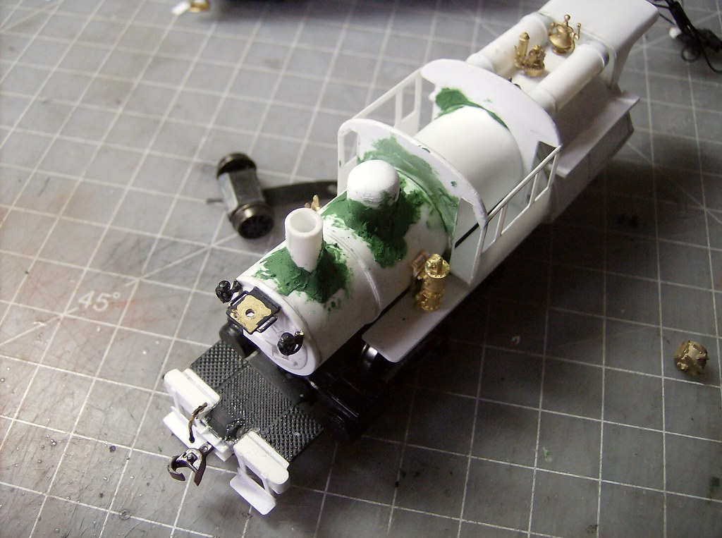
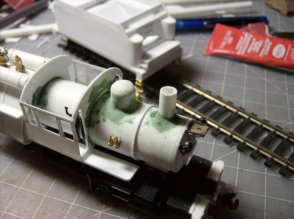
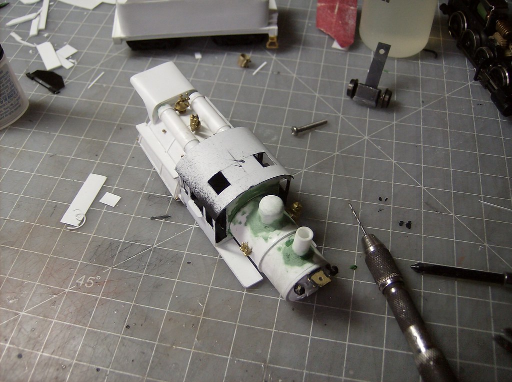
The sand dome is placed in the center of the short boiler section between the cab and smokebox. The dome started as .010 wrapped around several times and glued together with the outer seam then sanded flush. It was then capped with 2 layers of .040 and sanded round to finished the dome shape. Other parts appeared as I was waiting for things to dry.


Also while things were drying I got some finishing done on the pilot, first extending the coupler pocket and then making the footboards.


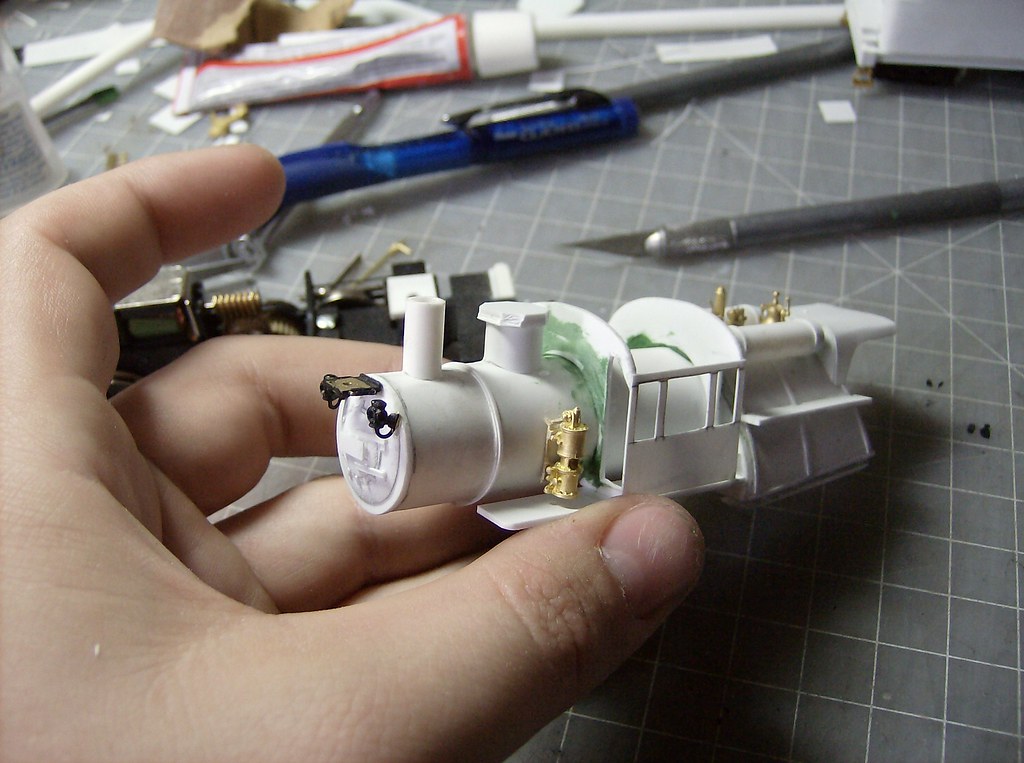
The stack and dome were then puttied and left to dry. After drying the putty was sanded.


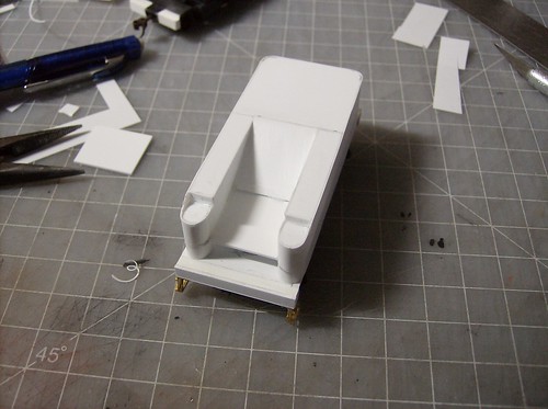
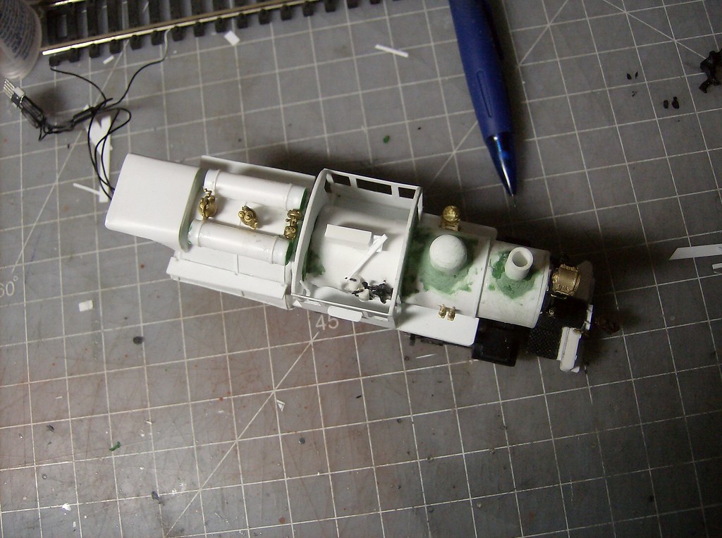
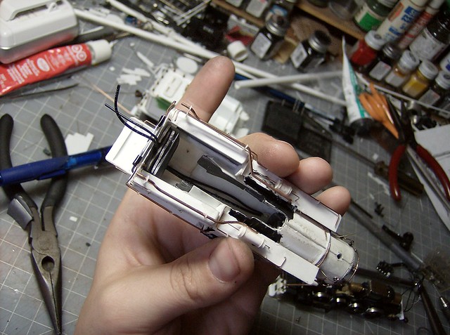
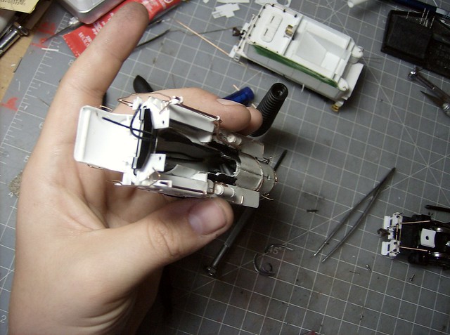
I wanted to do something for a cab interior on this one. Nothing too complex just something to give the idea of controls. The block in the center is quick steam dome, if you can manage to see it with the roof on. The injector lifter is a reused bachmann spectrum 2-8-0 piece.


I even dismembered and reassembled an old proto 2000 diesel figure for a cab figure. This one will be the first to have an engineer.


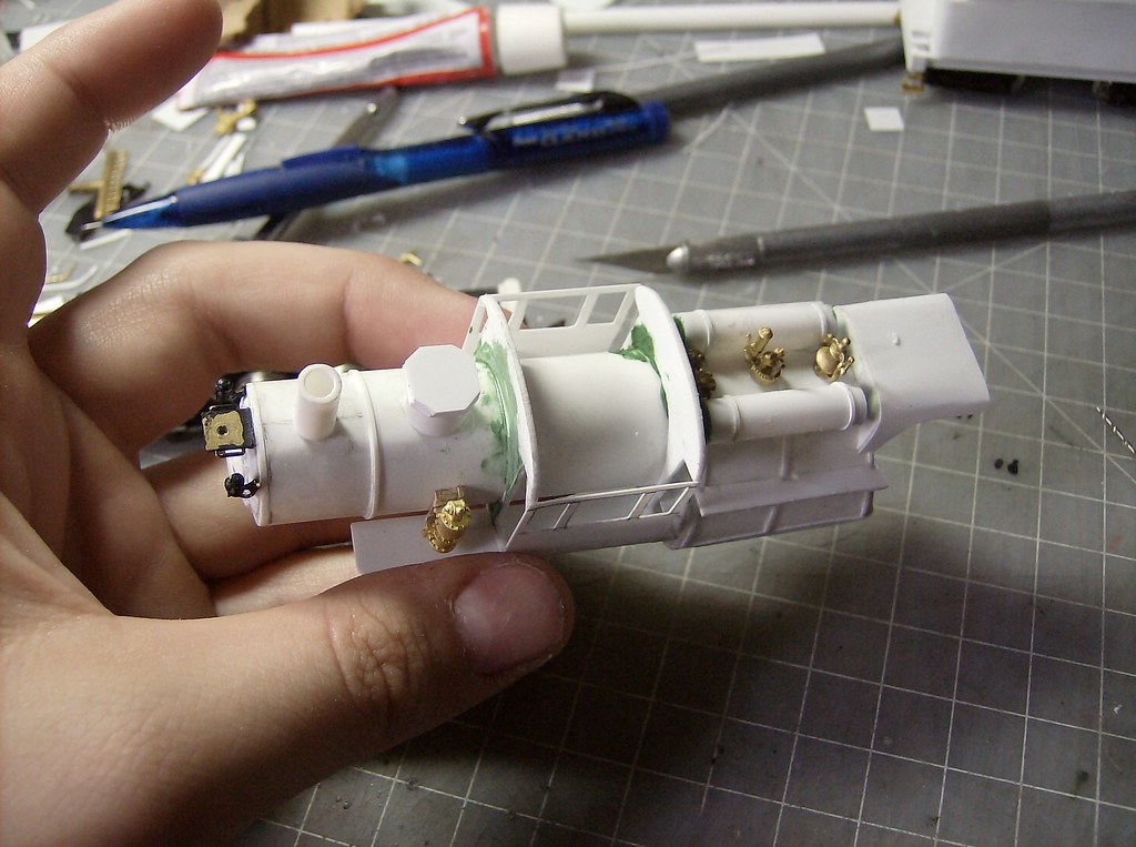
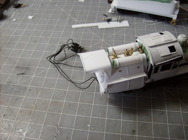
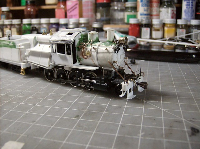
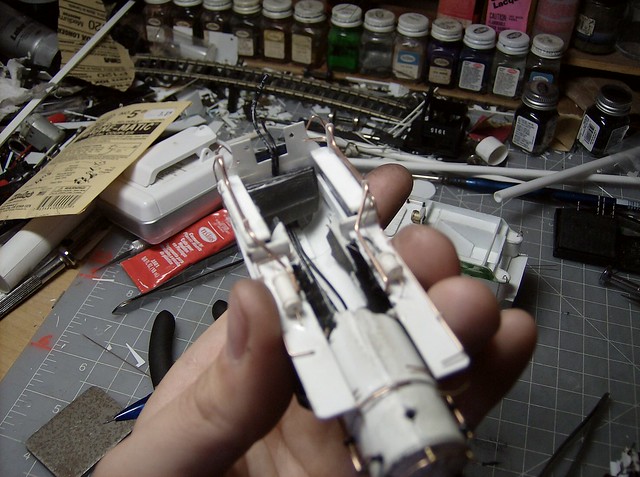
The roof is .010 fitted for the base dimensions then the center line is found and the vent holes are cut. Then the vents are placed on the glued down roof.


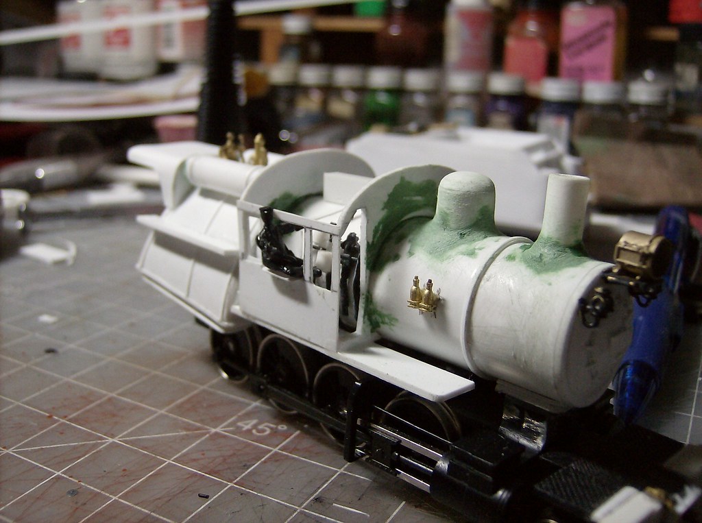
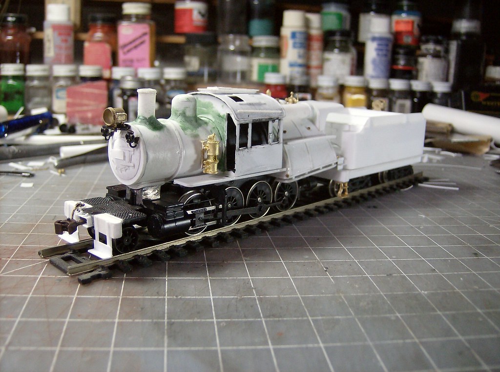
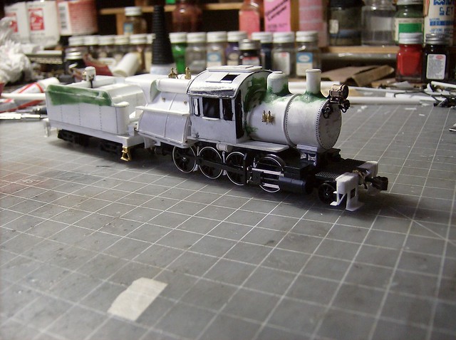
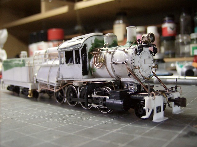
Heres where it sits now. There is still a bunch of little things to do before final detailing.

The administrator has disabled public write access.
The following user(s) said Thank You: Robin

Reading I-6 Build 8 years 11 months ago #4474

  • Casey
  • Casey's Avatar
  • OFFLINE
  • Conductor
  • Posts: 209
  • Thank you received: 57
With the major structures all done, most of the work to be done before adding plumbing is a lot of finishing edges and detail pieces. Work continued the tender making the water hatch and placing the rear headlight with the LED that came with the engine in place. The headlight protector I usually make out of brass to hold its shape in one piece I did in plastic to not short the leads of the LED.


The rear footboards and steps were built too at this time.


I then added the steps to the rear running boards on the firebox and made some fire doors. Then the a strip of .010 was put on the rear shade as trim.


Some putty was added to smooth the seam of the bunker before the trim on the tender was added. The images shows the trim in place around the top parameter.


The roundhouse engine did not come with break shoes so that is what I focused on next. This starts by drilling at least a divot on the frame for a piece of wire to be glued into in between the drivers.


Thin strips of .010 are drilled and cut to fit in between the drivers testing the driver movement.


Then small crescent shapes are made for the shoes themselves and glued inline with the wheel.


Then the rear ladder was made on the back of the tender, all .010.


With rivets placed it is now ready for plumbing and final detailing.

The administrator has disabled public write access.

Reading I-6 Build 8 years 11 months ago #4487

  • Casey
  • Casey's Avatar
  • OFFLINE
  • Conductor
  • Posts: 209
  • Thank you received: 57
The final detailing started with the tender, I added a number board in the process.


On the boiler the sander lines went down first then the air compressor was hooked up. I used a piece of "wrapped pipe" left over from a steam turret as the steam lead to the compressor.


Here is the fireman's side ready for paint.


The engineers side started the same way with sanders first, then the injector lines. The electric line to the markers and headlight starts at the little box on the cab front to the left marker light where I put a small junction box then it continues to the other marker light where another junction box is, seen on the previous picture. Its .010 wire with little .010 styrene squares.


Here is the engineers side ready to go.


For the sake of trying not to crush the details I was adding while I was doing them I added weight last from lead sheet pieces. I did what I could to where I knew it would not effect the motor or drive, but i didn't cram it in every place possible. Being a smaller engine if it does 15 cars I'll be happy.


The weather is supposed to be nice this week so I will probably start painting sooner then later.
The administrator has disabled public write access.
Time to create page: 0.134 seconds

Today's Image

Did You Know?

December 5, 1833
The Philadelphia and Reading (P&R) Railroad began operations.

Downloads

Operations Information

Click Here!A variety of Reading Company operations related documents, etc. that may be of use in your modeling efforts.

Operations Paperwork

Click Here!A variety of Reading Company operations paperwork, such as train orders, clearance forms, etc. that will help you operate your Reading layout in a prototypical manner.

Timetables, Rulebooks, Etc.

Click Here!Public Timetables, Employe Timetables, and Rulebooks that provide much useful operational information.

Modeling Goodies

Click Here!Signs, billboards, and other FREE goodies for your use.  We ask only that you help spread the word about The Reading Modeler!

Rolling Stock Reference

Click Here!Downloadable reference documents on the various classes of Reading Company Freight and Passenger rolling stock.

Thanks for Your Support!

If you find the content on The Reading Modeler valuable, won't you please consider supporting our efforts? Your donation will help to offset operating costs and acquire new material to share on the site. Thank you!

Amount: 

Advertisements