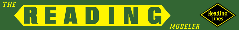
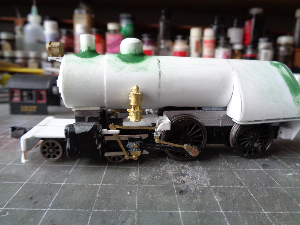
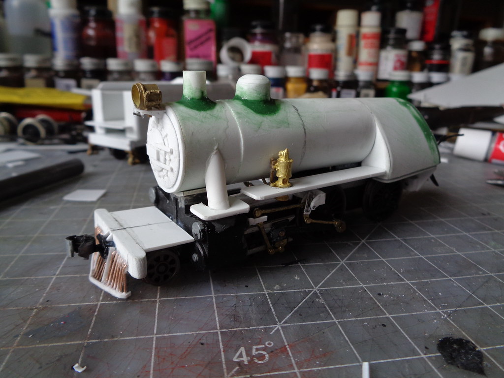
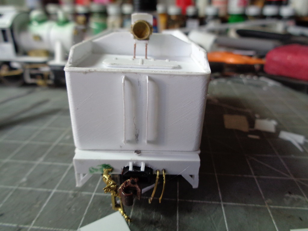
Before the cab was started, putty was added to make the base of the sand dome and stack. This is done before the cab so there is room to sand.
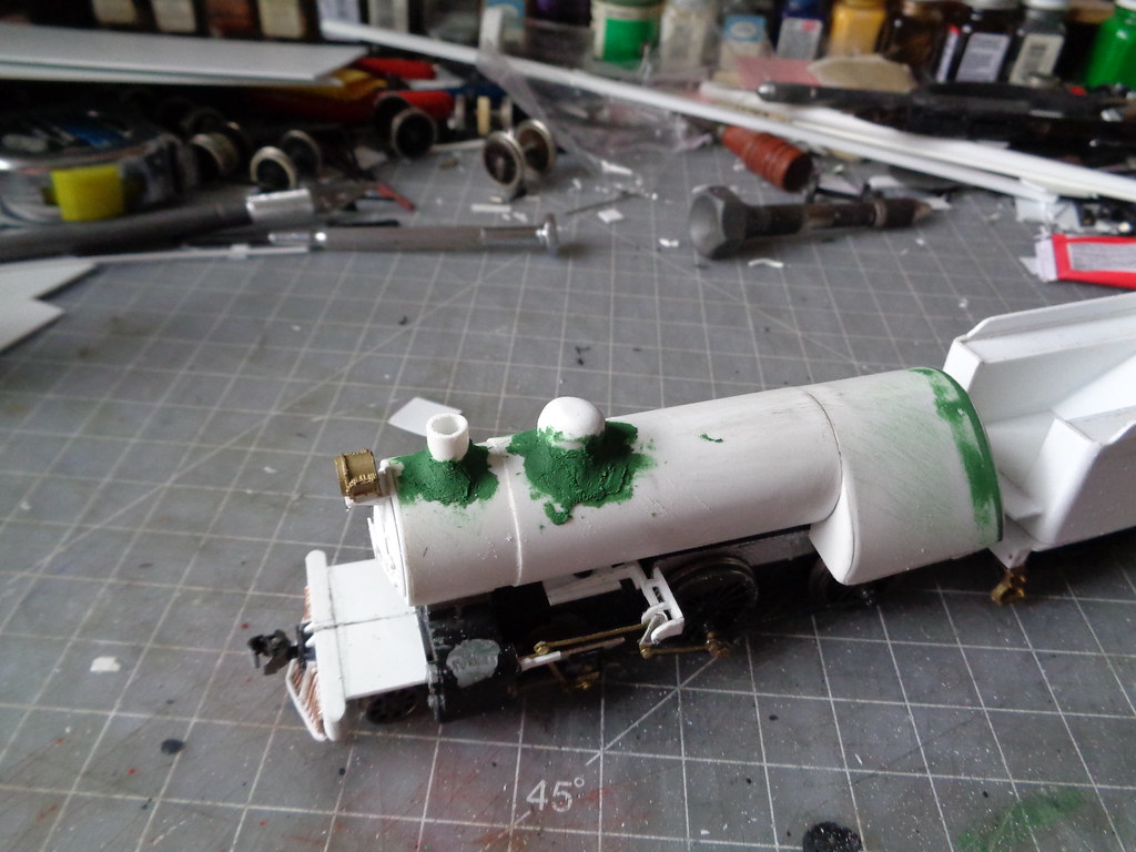
Before and after sanding...
The pencil mark on the boiler in the after sanded picture is to mark where the front wall is to sit for the cab. This is made easier by using a mantua camelback cab from the parts box as a bit of a template. Parts like these in general are very useful for reverse engineering.
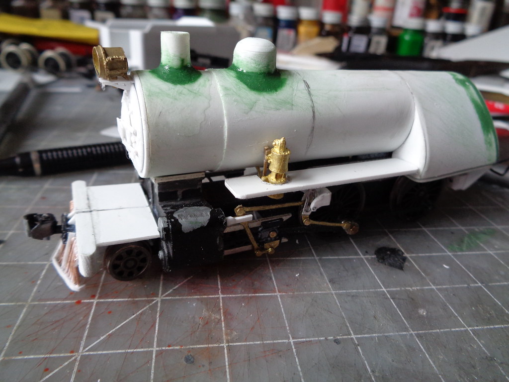
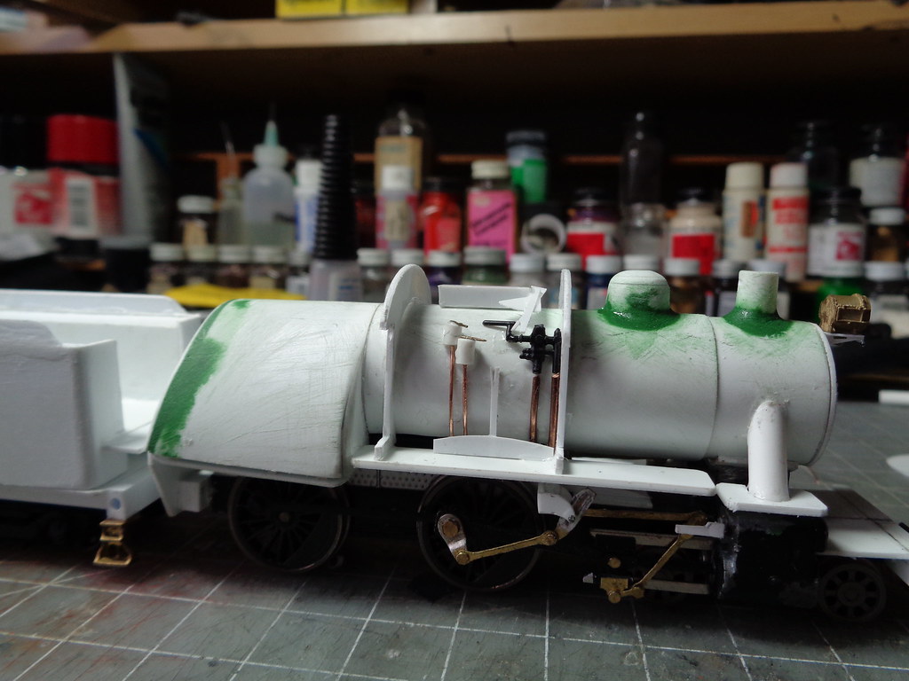
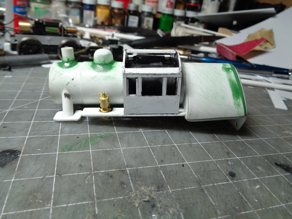
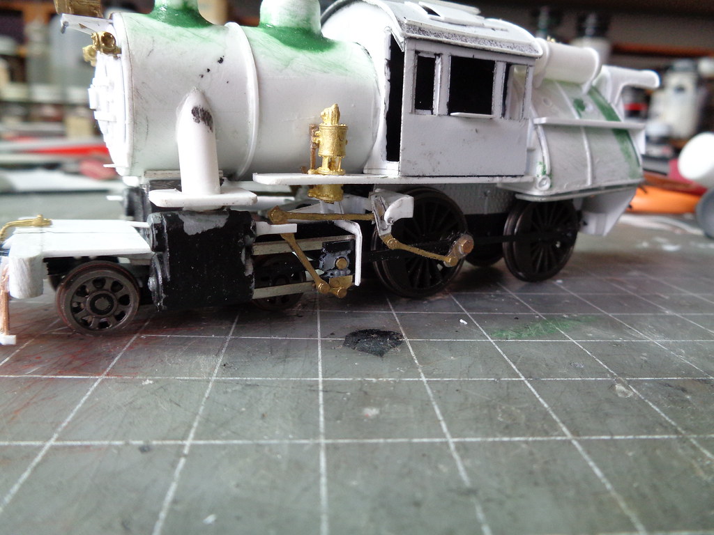
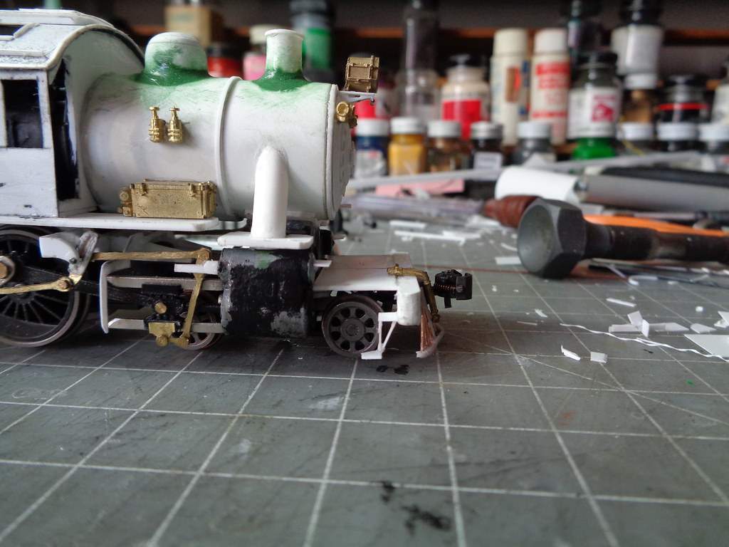
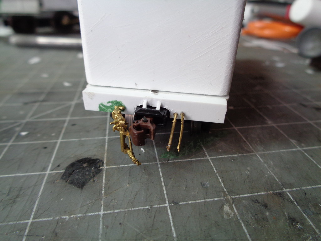
Getting ahead of myself a little attention went next to the running boards (which the cab sits on) but, to place the fireman's side properly the air compressor was placed since it sits so low on the running boards. The boiler mounting bracket that comes with the calscale single air compressor was used up side down to have the bracket rest on the boiler properly making a triangle mount.
The .040 for the running boards are cut to not exceed the width of the firebox. First glued to the front of the firebox and the fireman's side had the added glue point being able to tack it to the compressor itself. The engineer's side just needs to be looked after until set again glued to the front of the firebox. Once the cab is on the running boards are pretty solid.
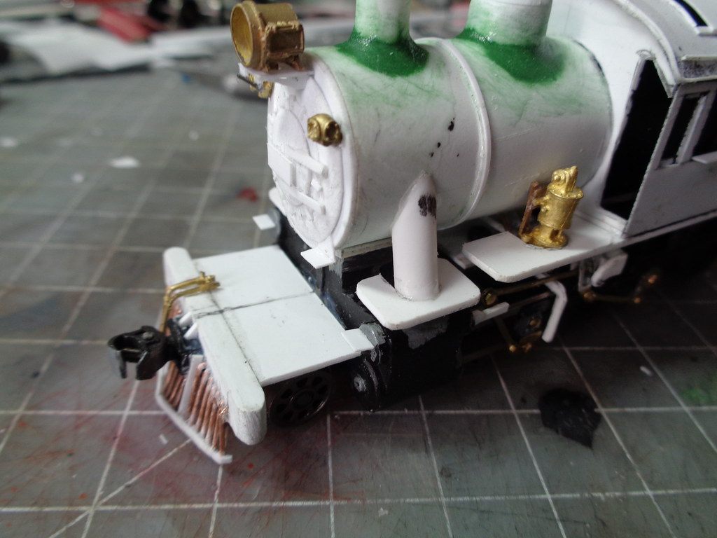
Using tube stock the steam delivery pipes are fitted which is a lot of test fitting and trimming until it looks right using a slow setting glue to tweak as needed. Then .040 running board pieces are notched to fit the pipe.
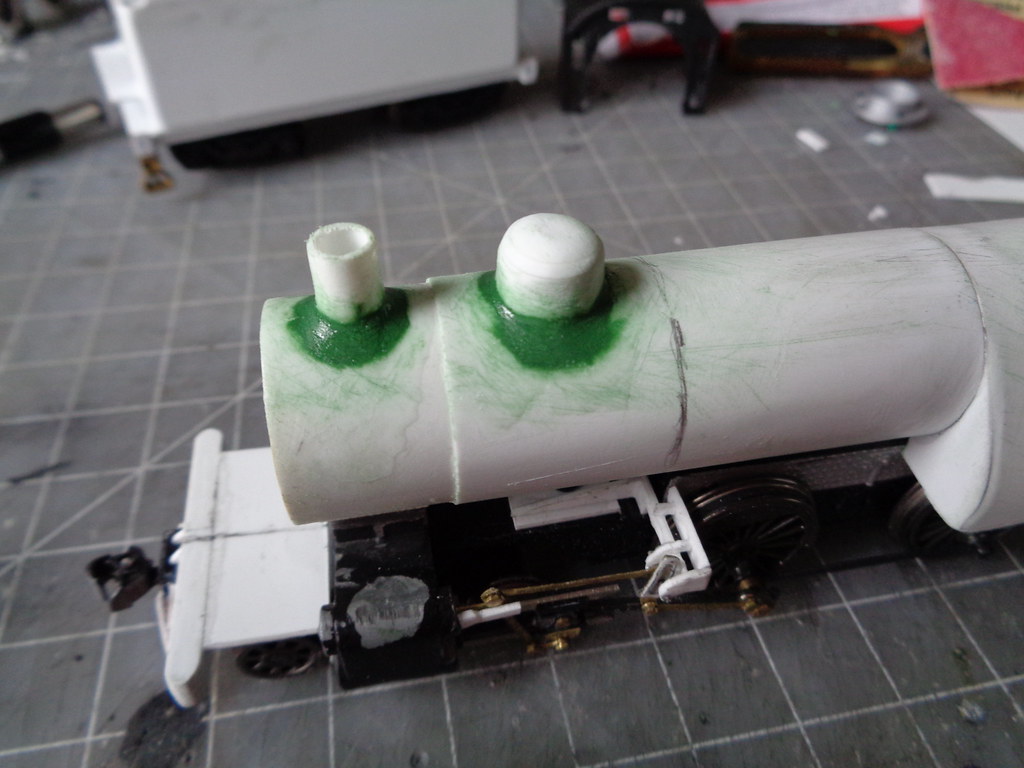
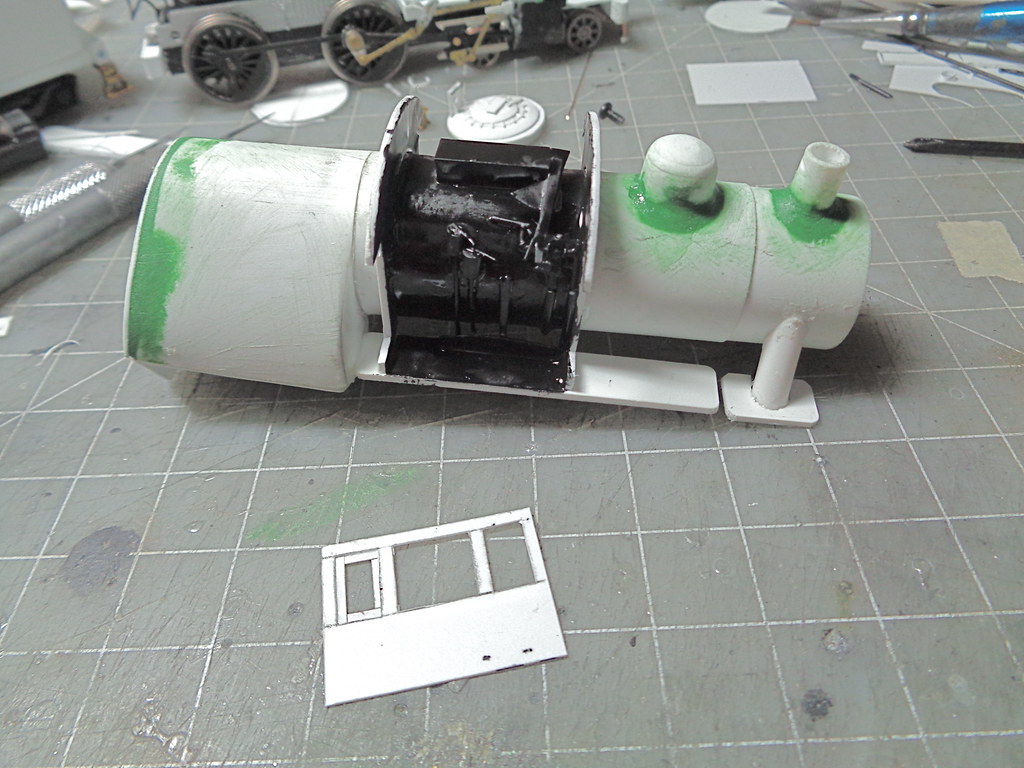
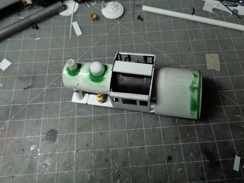
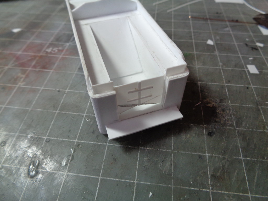
The front and rear walls of the cab are made by placing the boiler face down on .040 and tracing the outer dimension of the front, then find the center of that circle. having the running boards set you can easily measure the width which should be around the same as the firebox width, but .020 skinner to account for the cab sides. Using the center line on the circle made from the boiler front center the width measurement (half the total either direction) and you have a box centered on boiler. Using the mantua cab for measurements you can set the heights. After the basic shape is cut out the door openings are cut. The walls are then glued to the boiler, I use testors glue (red tube) for this because it does not set quickly and will help fill any minor gaps.
Trying something a little different I did the quick gist of cab controls and painted the cab interior before putting the cab sides on to help streamline the process and it makes it easier to paint.
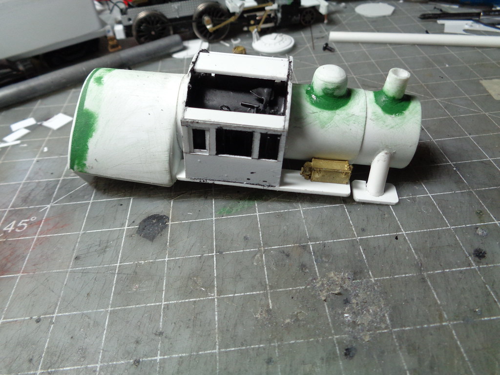
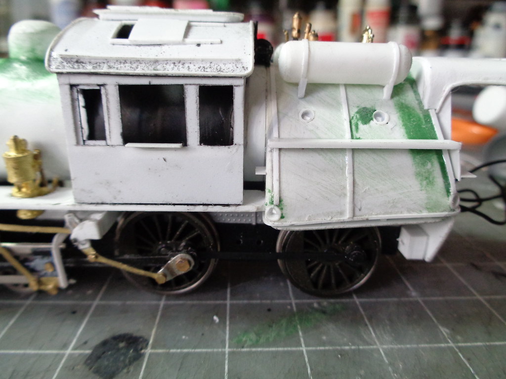
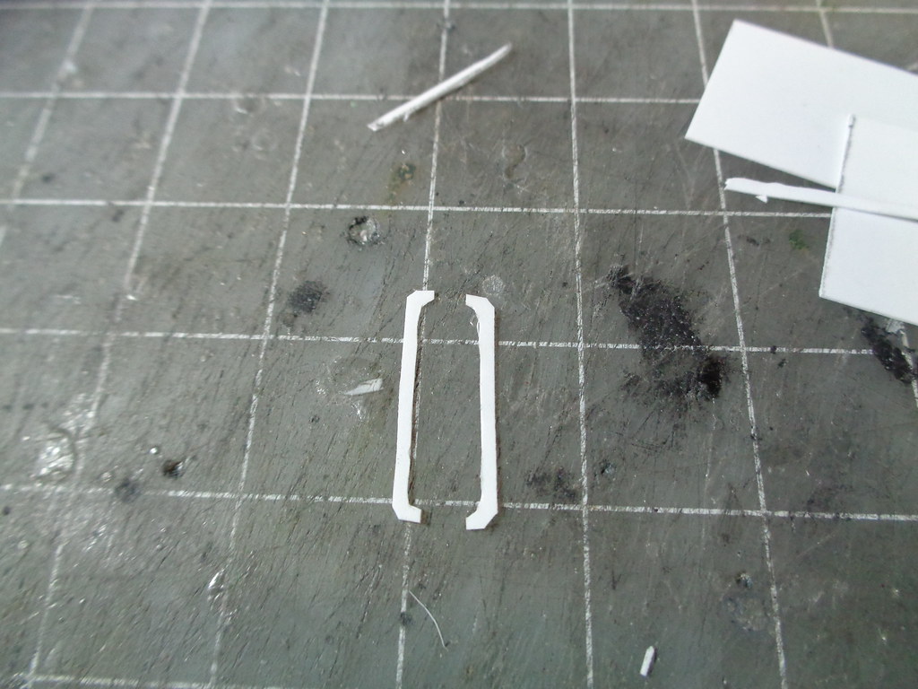
The .010 cab sides are made again using a mantua cab as a bit of a measurement template and the window frames (that the crew didn't take out) are placed, also .010.
After the sides are placed I have been adding some .040 supports to strengthen the roof and the top of the cab side from warping over time which can happen. Also the train control box was added for no reason, an optional part.
The roof is another part with a lot of test fitting before gluing down, the underside is also painted before gluing. The roof detail is then added, made mostly from .010 except the .040 spacer of the center hatch.
The rear running boards were then added cut to fit in line with the bottom of the windows of the cab and not to exceed the width of the firebox.
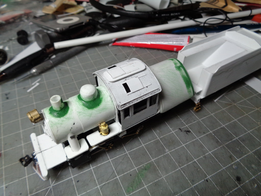
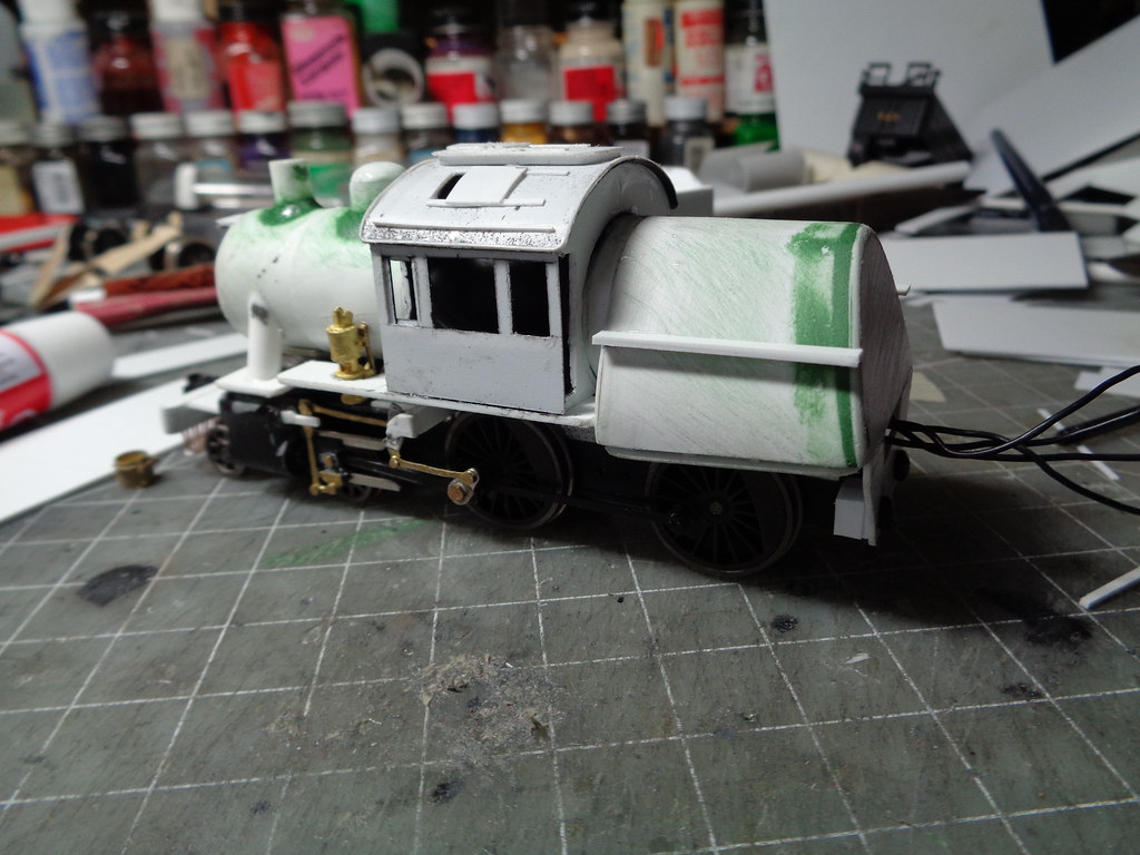
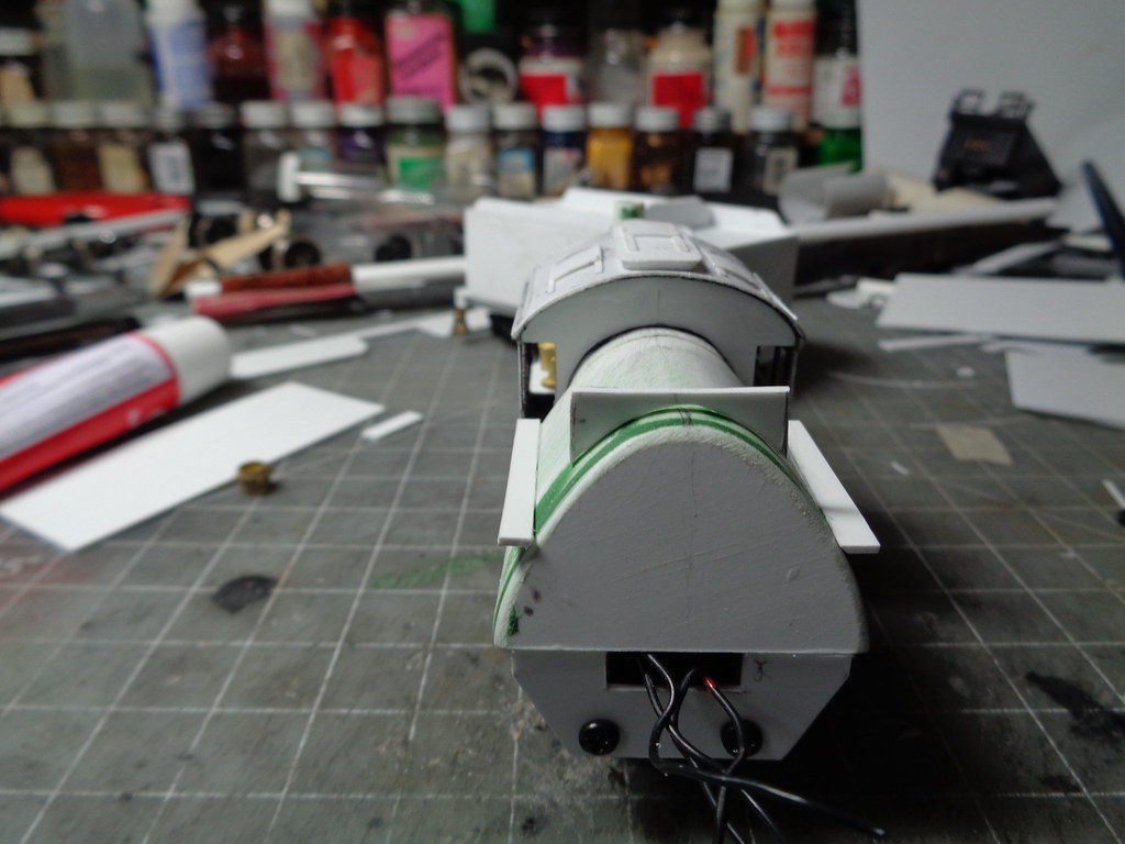
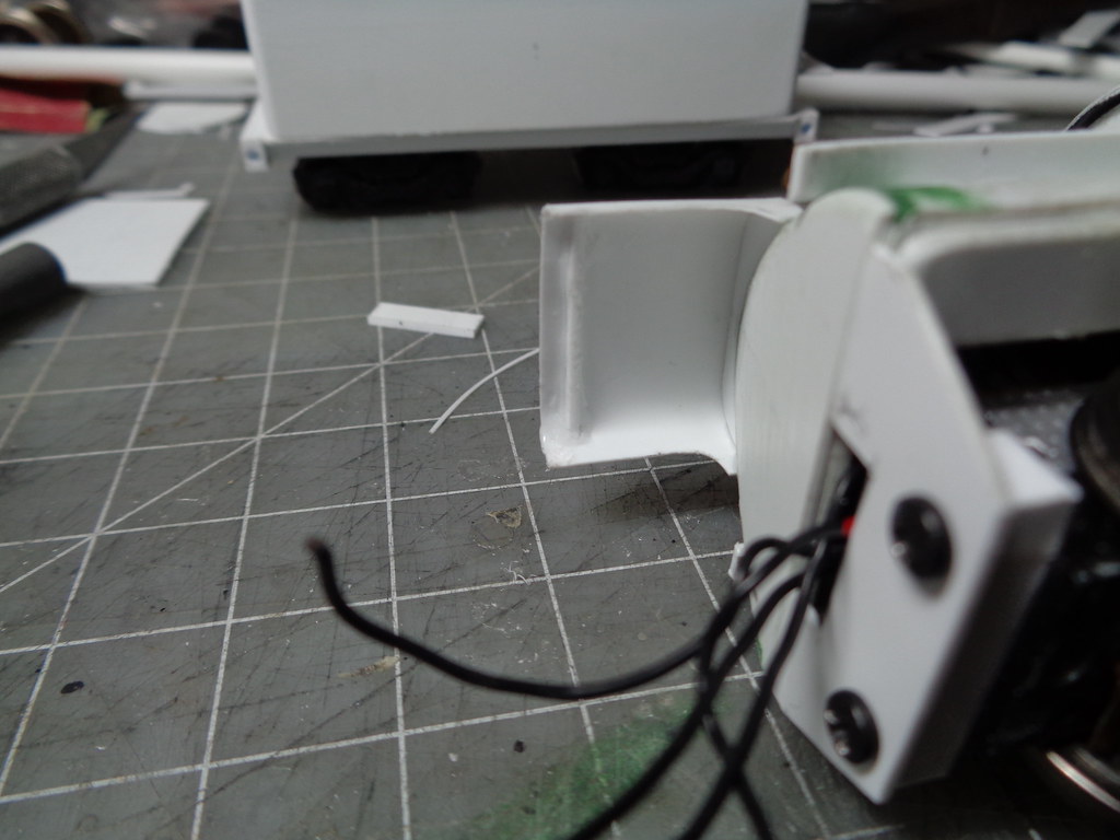
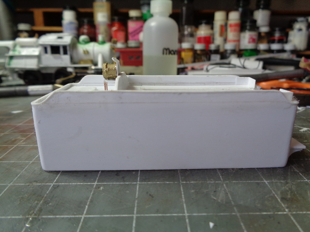
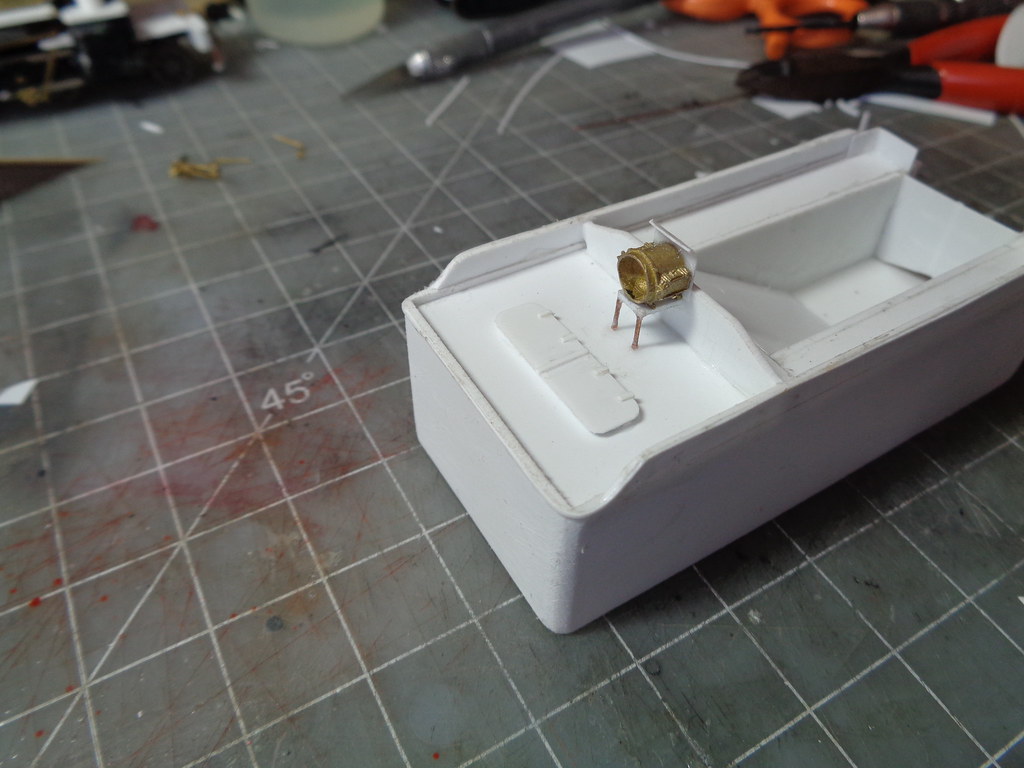
The rear shade or second cab starts like the center cab tracing the firebox to get the arc line. The width was eyeballed from the tender about as wide as the coal chute opening. Here is the test fit.
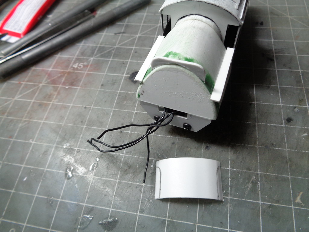
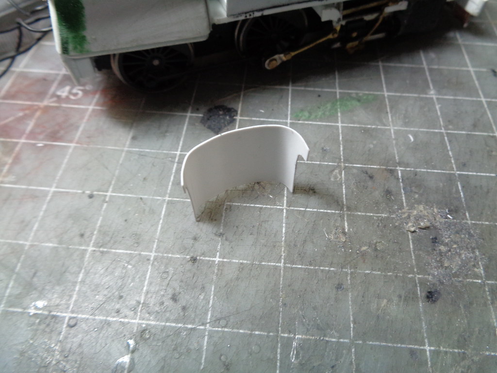
Another piece with a ton of test fitting the roof is bent and fit around the base glued to the edge of the firebox. The marks on the piece are what will be trimmed off.
The piece is then trimmed and glued in place. To hold the shape in the rear a little .040 support is fitted towards the rear.
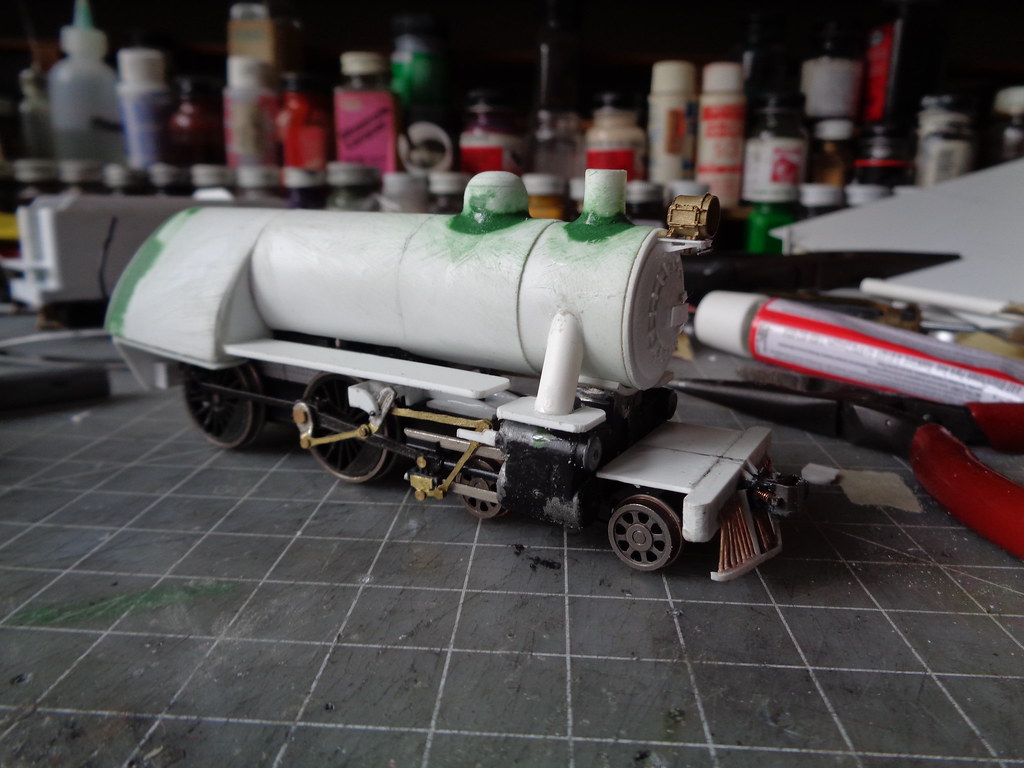
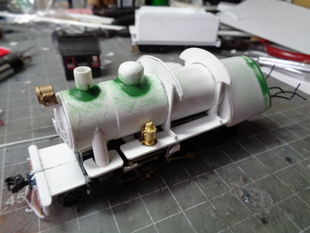
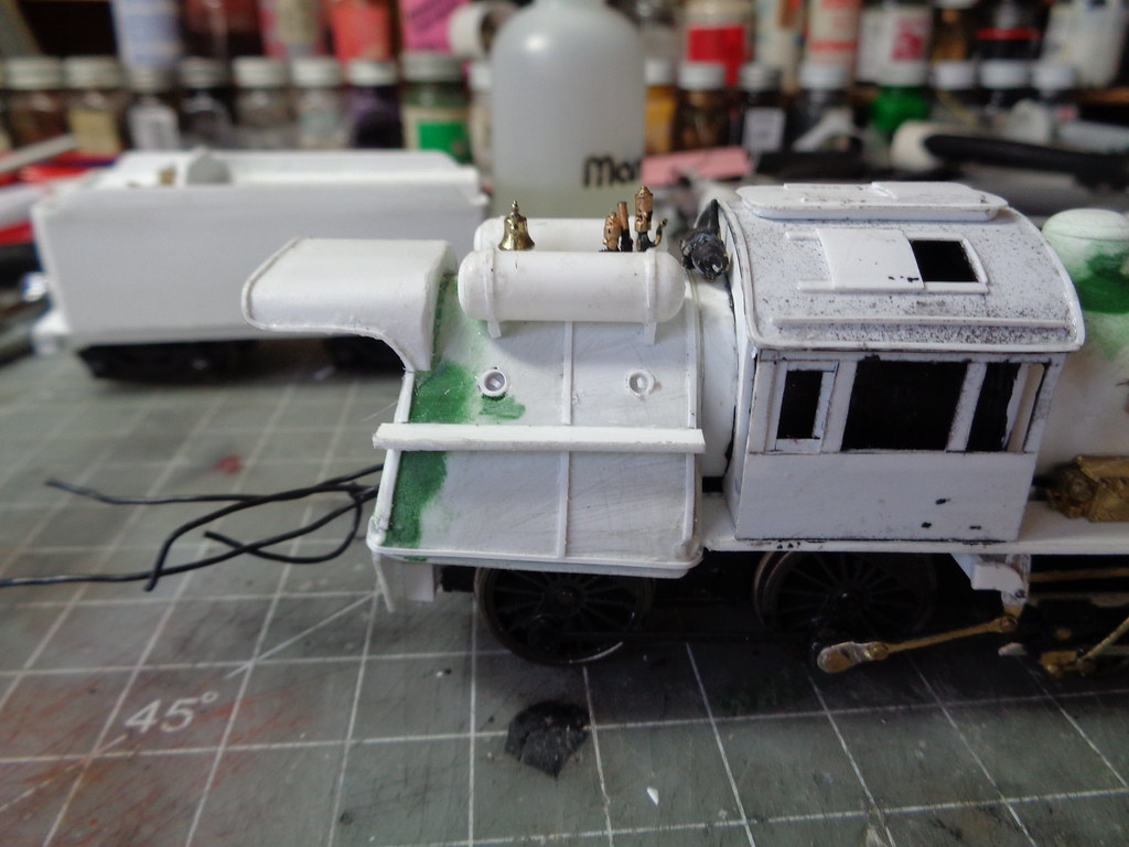
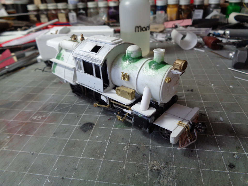
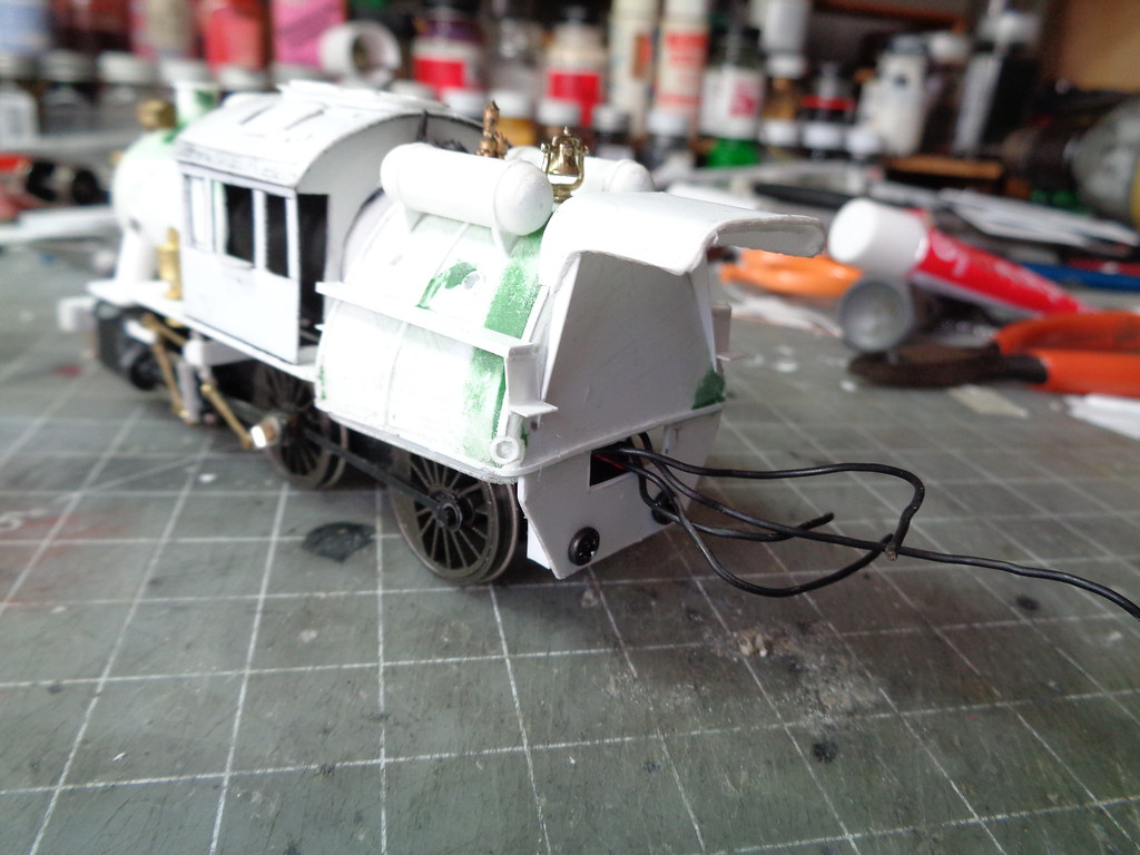
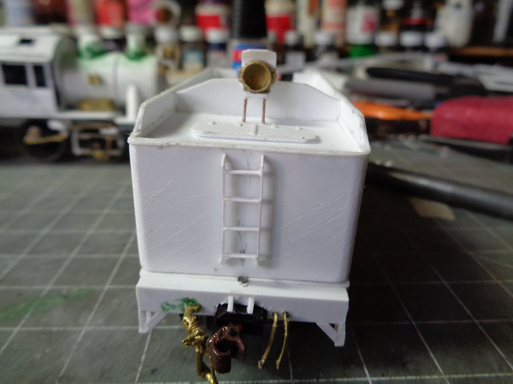
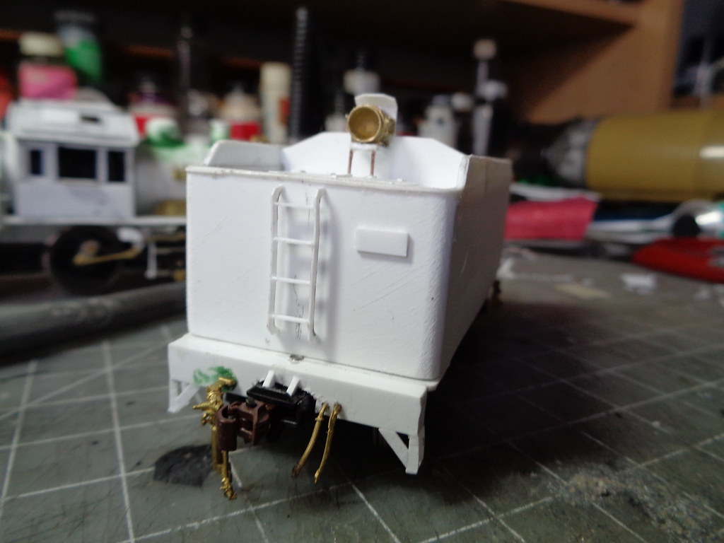
The air tanks were then fitted using tube stock. I tried a new method of capping the ends and sanding them round like the top of a dome. .010 was added to act as mounting straps as well as small .040 triangles to act as supports.
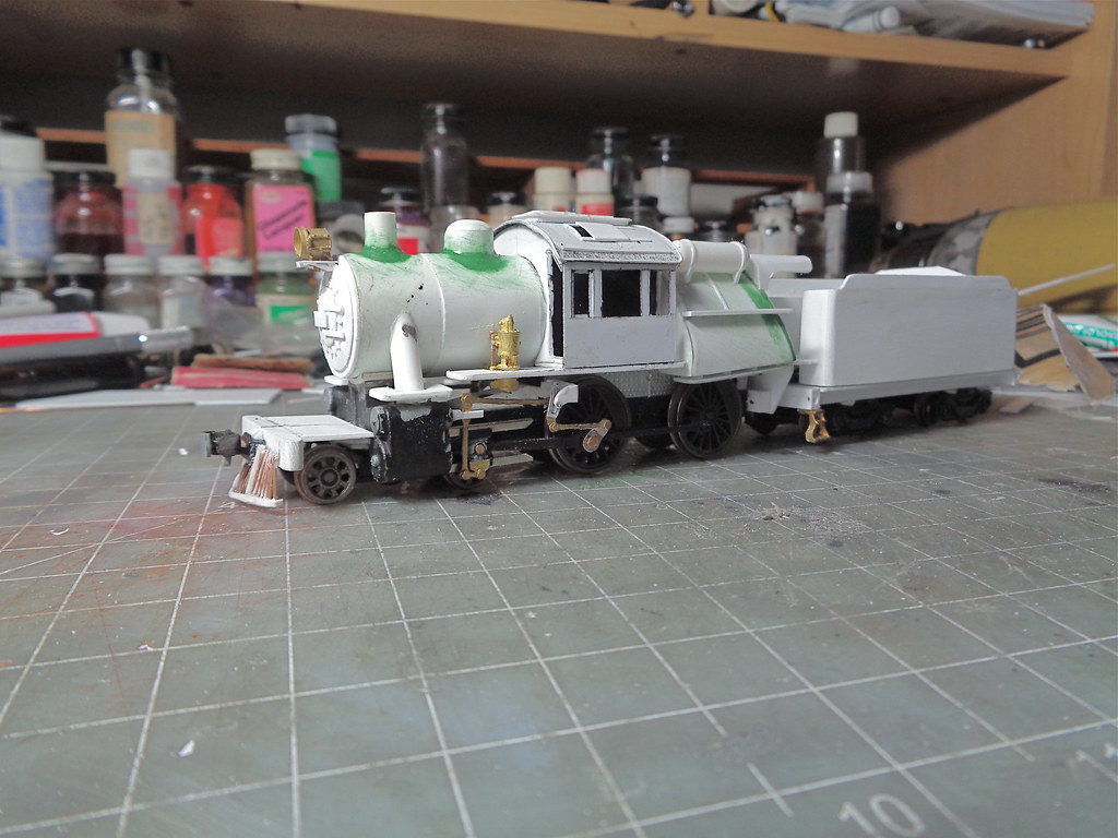
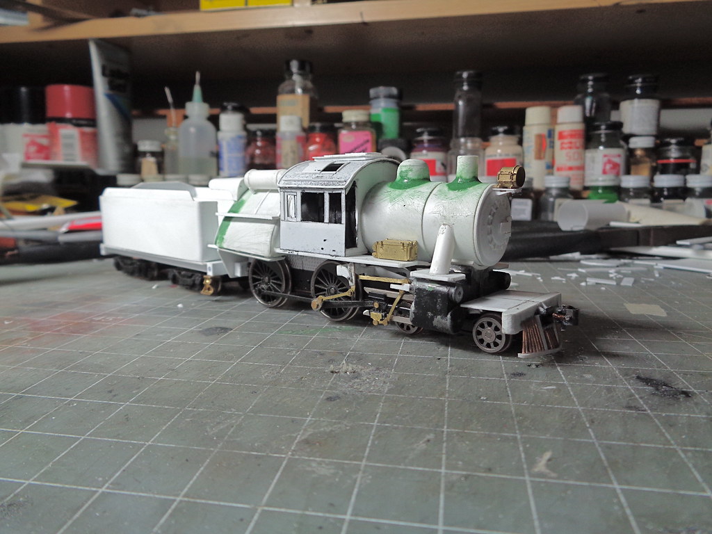
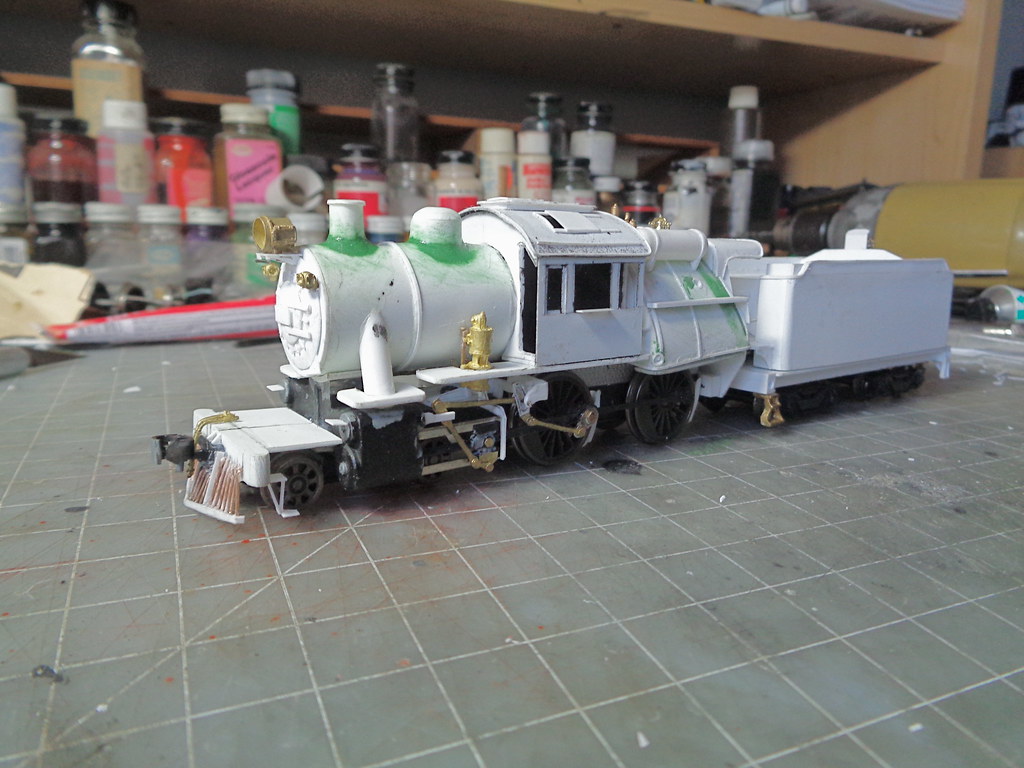
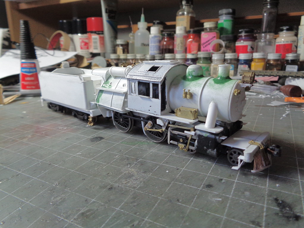
This is where the project sits now.


 A variety of Reading Company operations related documents, etc. that may be of use in your modeling efforts.