FacebookTwitterDiggGoogle BookmarksRedditLinkedinRSS Feed
Welcome, Guest
Username: Password: Remember me
This section of The Interchange provides a space where members of the Reading Modeler community can showcase their Reading modeling efforts. If you've got a project that you'd like to share, start a new topic and "show and tell" the group how you did it!

TOPIC: Lehigh Valley R-1 2-10-2

Lehigh Valley R-1 2-10-2 9 years 2 months ago #4160

  • Casey
  • Casey's Avatar
  • OFFLINE
  • Conductor
  • Posts: 209
  • Thank you received: 57
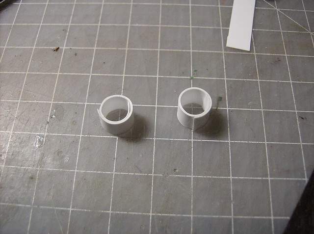
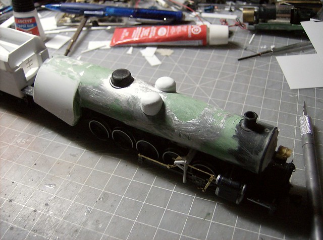
After a little more sanding I was ready to start the domes. .010 was looped around a couple layers that ended up the width of the existing steam dome and glued down at both ends.


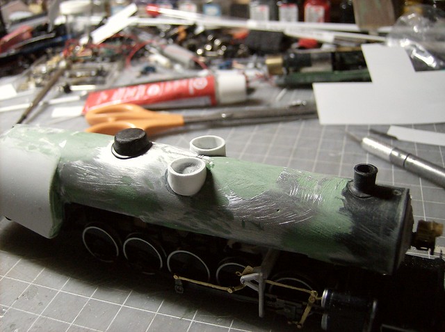
The seams were then sanded flush to made a smooth tube. Then the pieces were sanded to fit the boiler top and glued into place. After place they were sanded down from the top to be at the final height minus .080 of space which will make the caps.


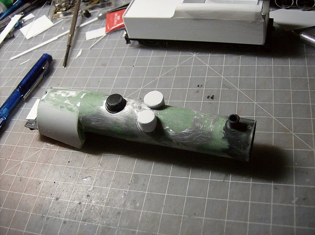
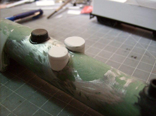
The caps start as 2 layers of .040 roughly cut and then sanded flush with the placed tube. Here you can see the sanded down (engineer's side) with the rough cut (fireman's side).


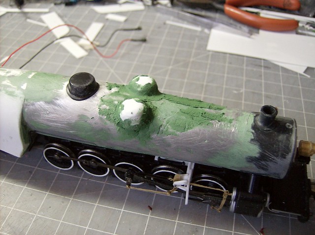
Then the tops get rounded to the final shapes.


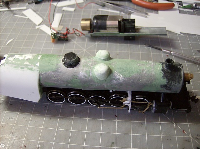
And more putty.


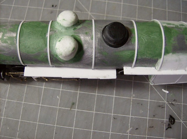
That putty is then smoothed out to make a rounded transition into the boiler.


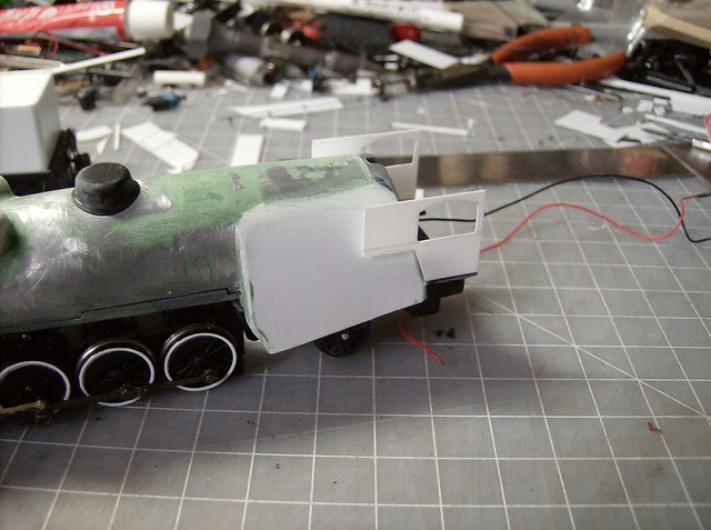
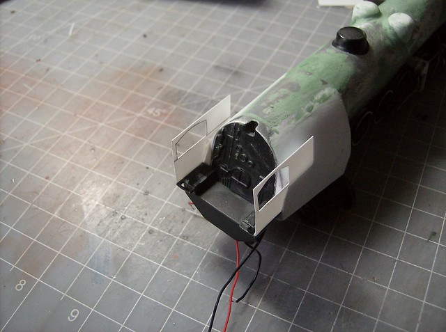
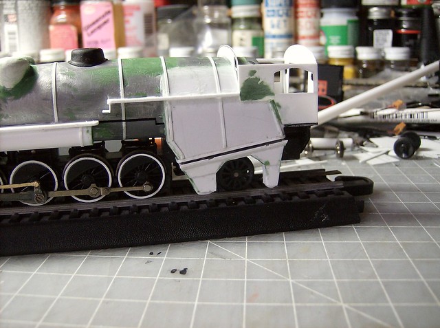
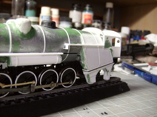
The cab started with the sides which were basically copies of the N-3's. Started as a 3/4"x 1 1/8" piece then got trimmed down. I bent the pieces inward just below the window with a pair of pliers at this point too to match the prototype and help line up the front and back when in place.


This is the back drawn out.


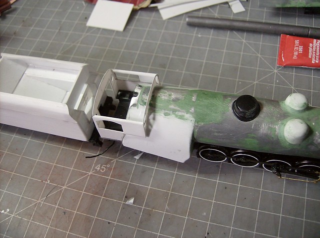
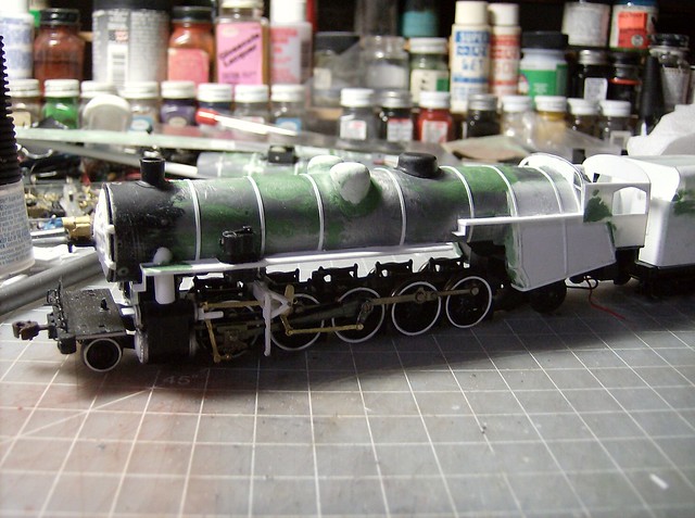
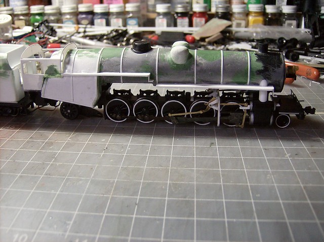
Here is the front and back in place which is done with a lot of holding up and small trims until it fits. A new technique is adding .040 railings above the windows to keep the cab inline.


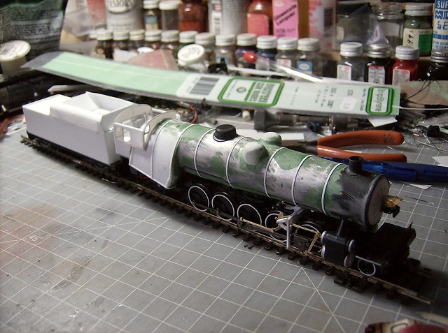
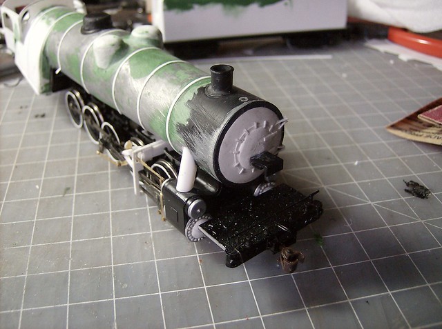
Then I got boiler bands in place which were wrapped all the way around the boiler then sliced at the seam.
The administrator has disabled public write access.

Lehigh Valley R-1 2-10-2 9 years 1 month ago #4234

  • Casey
  • Casey's Avatar
  • OFFLINE
  • Conductor
  • Posts: 209
  • Thank you received: 57
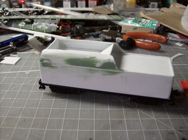
Some more putty work was needed to get rid of the seam of the coal bunker. Nothing crazy just enough to smooth it out.


After sanding.


Before starting the running boards I wanted to set the steam delivery pipes higher which were made from a styrene tube. They are attached to the boiler, not the cylinders. They don't have to be glued that way, that is just what I prefer.


The space over the first driver is where the compressor goes and I was originally going to do one piece for the front half the running boards, but having issues getting a piece to fit I ended up doing 3 pieces which is the easier way.


Also a minor technique, if you finally get a piece to fit but a little too much was trimmed off one end I add back with strips instead of making a new piece. Gluing a few layers then sanding flush and to the desired size when dry. This is one of the big reasons I like working in plastic, being able to fix on the fly.


This is the main running board pieces in place for the fireman's side with the compressor in place. The compressor is a plastic one off the proto 2-8-8-2.


Then the steps were added made from .010.


The engineers side was easier without the compressor in the way.


With the running boards done the air tanks can get installed. Other parts were put on as well. The check valves are the original bachmann ones.


Next work was started on the ash pans. The base .040 piece was glued to the bottom of the limited bachmann ash pan detail then a .010 frame was built on the bottom of that. The opening was spaced around the wheel checking the clearances of the rear wheel. I made sure it would turn for at least 22" radius.


With the fame in the rest was built out. The little bits of putty filed holes it wasn't worth making pieces to cover.


With that built the engineer's side is just making copies of the fireman's side pieces and slapping it together.
The administrator has disabled public write access.
The following user(s) said Thank You: Robin

Lehigh Valley R-1 2-10-2 9 years 1 month ago #4235

  • Turboboost910
  • Turboboost910's Avatar
  • OFFLINE
  • Conductor
  • Posts: 250
  • Thank you received: 17
I love the progress! you really do give me motivation to hurry up and finish my I-10sa so I can get back to work on my T-1...
The administrator has disabled public write access.

Lehigh Valley R-1 2-10-2 9 years 1 month ago #4236

  • Robin
  • Robin's Avatar
  • OFFLINE
  • Conductor
  • Posts: 173
  • Thank you received: 47
It's great watching your progress, Casey. It's both informative and inspirational. BTW, what would you do with a Roundhouse (Athearn era) old timer 2-8-0? I'm thinking I-3 or I-5. It seems too small for an I-7.
Last Edit: 9 years 1 month ago by Robin.
The administrator has disabled public write access.

Lehigh Valley R-1 2-10-2 9 years 1 month ago #4237

  • Casey
  • Casey's Avatar
  • OFFLINE
  • Conductor
  • Posts: 209
  • Thank you received: 57
I think any of those would work. I have been wanting to pick up 2 myself to do and I-6 and I-7. The model based on the Maryland and Pennsylvania is supposed to have 50" drivers though I'm not totally sure they are scaled perfectly. There is a difference between the roundhouse PRR E-6 and the bowser PRR E-6 drivers. (I have parts of both kits) All said too, 5 inches of HO scale space is not very much.
The administrator has disabled public write access.

Lehigh Valley R-1 2-10-2 9 years 1 month ago #4238

  • Casey
  • Casey's Avatar
  • OFFLINE
  • Conductor
  • Posts: 209
  • Thank you received: 57
Robin to expand on your question more I did a little research on the roundhouse engines and found the driver size listed as 52" and the 0-6-0 driver size is the same, one of which I happen to have.

You can see the drivers are bigger then proto 2000 50" drivers.


Seen here being smaller then the N-1s drivers which I am passing off as 55", but if the scaling is right USRA 2-8-8-2 drivers are supposed to be 57".


So I stick by what I said, they are in between 50 and 55 and would work for basically anything from I-2 to I-7.
The administrator has disabled public write access.
The following user(s) said Thank You: Robin
Time to create page: 0.118 seconds

Today's Image

Did You Know?

January 1, 1955
The Reading begins Trailer-on-Flatcar (TOFC) service between Philadelphia and Chicago in cooperation with the WM, P&WV, and NKP (the "Alphabet Route").

Downloads

Operations Information

Click Here!A variety of Reading Company operations related documents, etc. that may be of use in your modeling efforts.

Operations Paperwork

Click Here!A variety of Reading Company operations paperwork, such as train orders, clearance forms, etc. that will help you operate your Reading layout in a prototypical manner.

Timetables, Rulebooks, Etc.

Click Here!Public Timetables, Employe Timetables, and Rulebooks that provide much useful operational information.

Modeling Goodies

Click Here!Signs, billboards, and other FREE goodies for your use.  We ask only that you help spread the word about The Reading Modeler!

Rolling Stock Reference

Click Here!Downloadable reference documents on the various classes of Reading Company Freight and Passenger rolling stock.

Thanks for Your Support!

If you find the content on The Reading Modeler valuable, won't you please consider supporting our efforts? Your donation will help to offset operating costs and acquire new material to share on the site. Thank you!

Amount: 

Advertisements